Soldering Procedures for Chip Components on PCBs: Soldering Process for SMD Components
1.Cleaning and securing the PCB
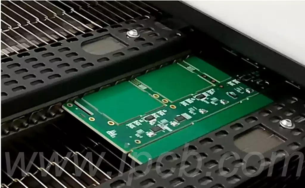
Before soldering the PCB, the first task is to ensure the cleanliness of the PCB boards. Any oily fingerprints and oxides must be removed to prevent negative effects on the soldering. When soldering PCBs manually, if conditions permit, a fixing device such as a soldering table can be used to facilitate the soldering operation. Often, fixing by hand is also feasible, but care must be taken that the fingers should not touch the pads on the PCB to avoid affecting the quality of the soldering.
2.Fixing SMD components
Fixing the SMD assembly is a critical step in the soldering process. Depending on the number of pins in the component, the fixing method varies. For SMD components with a small number of pins (usually 2-5 pins), such as resistors, capacitors, diodes, transistors, etc., the single-pin fixing method is often used. This means that the solder is first preset on one of the PCB’s pads, and then the component is held using tweezers, placed in a predetermined position and gently secured. Subsequently, a soldering iron is used to touch the pad and melt the solder to solder the pin. Once the component is secured on the pad, the tweezers can be released.
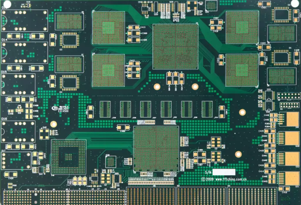
For SMD chips with many pins spread over multiple sides, the multi-pin fixing method is often used due to the difficulty of fixing them with a single pin. This usually involves first soldering a pin, and then soldering the pin opposite the pin, thus realizing the fixation of the entire chip. It is important to note that for chips with many and dense pins, precise alignment of the pins with the pads is critical and should be carefully checked, as the quality of the solder depends on this prerequisite.
It is especially emphasized that the pins of the chip must be correctly identified. Sometimes, even if we have carefully secured the chip and even completed the soldering, we find during inspection that the pins correspond incorrectly – i.e., a pin that is not the first pin has been misused as the first pin to be soldered. Therefore, these careful preliminary tasks should never be sloppy.
3.Soldering the remaining pins
After fixing the circuit board components, the next step is to solder the remaining pins. For components with fewer pins, you can hold the solder in your left hand and the soldering iron in your right hand, and spot weld them sequentially. For chips with many pins and dense, in addition to spot soldering, you can also use drag soldering method, that is, place enough solder on a pin, and then use the soldering iron to melt the solder to the other pins on that side. The melted solder can flow, so sometimes the board can be tilted properly to remove excess solder. It is important to note that both spot and drag soldering can easily result in adjacent pins being shorted by the solder. However, this situation can be resolved. The key is to make sure that all pins are well connected to the pads and that there is no under-soldering.
4.Removing Excess Solder
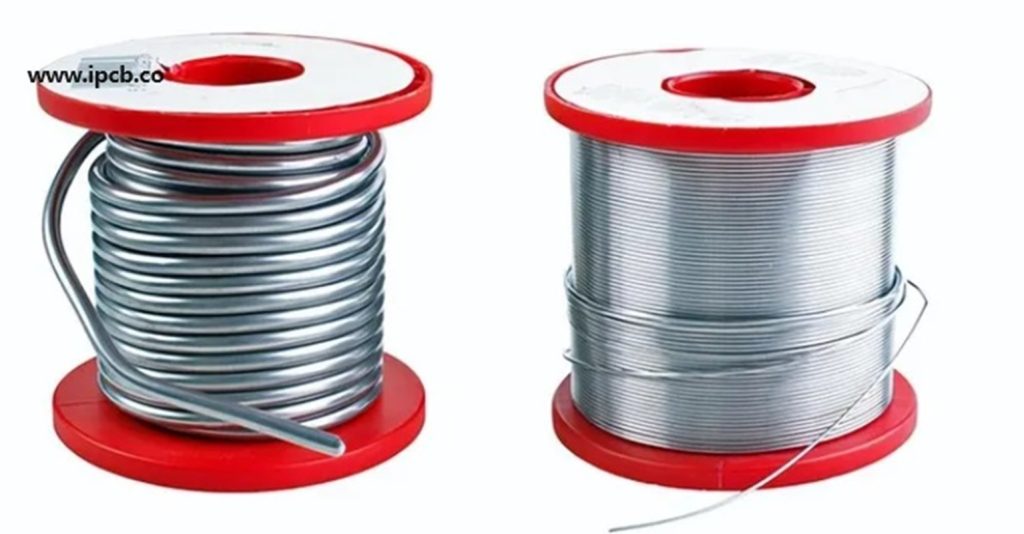
In step 3, we mentioned short-circuiting caused by solder. Now let’s discuss how to deal with excess solder. Usually, you can use the solder suction tape mentioned above. It is easy to use a solder suction tape, just add the right amount of flux (e.g. rosin) to the tape and place it close to the pads. Place a clean soldering iron tip on the tape and wait for the tape to heat up to absorb the solder from the pads. When the solder has melted, pull it slowly from one end of the pad to the other and the solder will be sucked into the suction tape. Note that when soldering is complete, both the soldering iron tip and the tape should be removed from the pad at the same time. Then add flux again or reheat with the soldering iron tip on the suction tape, and then gently pull the suction tape to disengage it from the pad to prevent the surrounding PCB components from being burned. If there is no specialized tin tape on the market, you can use the thin copper wire in the wire to make their own tin tape. Homemade method is as follows: peel off the outer skin of the wire, exposing the inside of the fine copper wire. At this point, use a soldering iron to melt some rosin on the copper wire. In addition, if you are not satisfied with the soldering result, you can reuse the solder absorbing tape to remove the solder and then re-solder the component.
5.Cleaning the soldering area
After the PCB is soldered and excess solder is removed, the chip is essentially soldered. However, due to the use of rosin for soldering and solder suction tape, some rosin residue may remain on the board around the chip pins. Although these residues do not affect the operation and normal use of the chip, they may not be aesthetically pleasing and may cause inconvenience during inspection. Therefore, it is necessary to remove these residues. A common cleaning method can be the use of cleaning board water. Here, we use alcohol for cleaning. Cleaning tools can be cotton swabs or toilet paper with tweezers. When cleaning and wiping, it should be noted that the amount of alcohol should be moderate, and its concentration should preferably be high in order to quickly dissolve the rosin and other residues. Secondly, wipe the strength to control, not too large, so as not to scratch the soldermask and damage the chip pins. At this point, you can use a soldering iron or hot air gun to properly heat the alcohol scrubbing position, so that the residual alcohol evaporates quickly. At this point, the chip welding work has been completed.