For electronic equipment, work will produce a certain amount of heat, so that the internal temperature of the device rises rapidly, if the heat is not promptly distributed, the device will continue to heat up, the device will fail due to overheating, and the reliability of the electronic equipment will decline. Therefore, PCB Thermal treatment is very important.
PCB thermal methods:
- Highly heated components with heat sinks and thermal panels
When there are only a few (less than 3) high-heat components on the PCB, heat sinks or heat pipes can be added to assist in heat dissipation. If the temperature is still difficult to control, it is recommended to use a heat sink with a fan. And when there are more high heat components (more than 3), it is recommended to use a large heat sink or heat plate, the design of which should be based on the layout and height of the components. However, the heat dissipation effect may not be ideal due to the difference in height of the components when they are soldered. In this case, consider adding a soft thermal phase change thermal pad on the component surface to enhance heat dissipation.
- Utilizing the circuit board itself to dissipate heat
Currently used circuit board substrates, such as copper/epoxy glass cloth substrate or phenolic resin glass cloth substrate, its thermal performance is relatively weak. These substrates mainly rely on the component surface to the air heat dissipation, rather than through the substrate itself. With the trend toward miniaturization, high-density mounting, and high heat generation in electronic products, it is no longer possible to meet the demand by relying only on the surface of the component to dissipate heat. Therefore, it is crucial to improve the heat dissipation ability of the PCB itself, which is in direct contact with the heat-generating components.
- Reasonable wiring to achieve heat dissipation
Since the resin in PCBs has poor thermal conductivity, copper foil lines and thermal vias are excellent heat conductors. Therefore, increasing the residual rate of copper foil and increasing the number of heat-conducting holes are key means to enhance heat dissipation. In order to evaluate the heat dissipation capability of a PCB, the equivalent thermal conductivity of a circuit board insulating substrate composed of materials with different thermal conductivity needs to be calculated.
- Device Layout for Free Convection Cooling
For devices using free convection air cooling, it is recommended that integrated circuits or other devices be arranged in a longitudinal or cross-length manner.
- Partition layout of heat generating components
On the same PCB, the layout should be partitioned according to the heat generation and heat dissipation performance of the components. Will heat small or poor thermal components placed in the cooling airflow inlet, and will heat large or good thermal components placed in the downstream.
- Optimize the layout of components on the PCB
In the horizontal direction, high-power devices should be arranged close to the edge of the PCB to shorten the heat dissipation path; in the vertical direction, try to be placed on top of the PCB. Temperature-sensitive devices should be placed in the lowest temperature region, avoid placing in the heat element directly above. Multiple devices should be staggered layout to avoid hot spot concentration.
- Consider the air flow path layout PCB
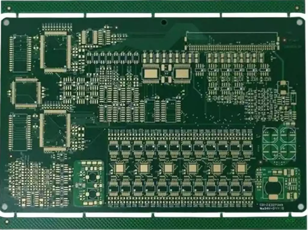
PCB heat dissipation depends mainly on air flow, so the design needs to consider the air flow path. Avoid leaving a large blank area on the PCB to prevent obstruction of air flow. At the same time, the layout of multiple PCBs in the machine should follow the same principle.
- Uniform distribution of power to reduce hot spots
In PCB design, should try to avoid excessive concentration of power, and strive for uniform distribution of power to maintain the consistency of the PCB surface temperature. Although it may be difficult to achieve a strict uniform distribution, but should strive to avoid the emergence of high power density areas, in order to prevent the normal operation of the circuit. If conditions permit, PCB thermal efficiency analysis will help improve the design.
- Optimized layout of high heat components
Components that consume the most power and generate the most heat should be placed near the location with the best heat dissipation. Avoid placing hot components in the corners or edges of the PCB unless there is a heat sink nearby. When designing power resistors, select larger components whenever possible and allow enough space for them to dissipate heat when adjusting the PCB layout.
- Reduce the thermal resistance between the component and the substrate
High heat dissipation components in connection with the substrate, should minimize the thermal resistance between them. To improve the thermal characteristics, use thermally conductive materials on the bottom surface of the chip and ensure that there is enough contact area for the components to dissipate heat.
- Optimize the connection between components and the substrate
When connecting components to the substrate, the lead length of the components should be shortened as much as possible; when selecting high power components, the thermal conductivity of the lead material should be considered, and if possible, the lead with the largest cross-section should be selected; and priority should be given to the selection of components with a larger number of pins.
- Principles of component package selection
In the thermal design, attention should be paid to the component package description and its thermal conductivity; between the substrate and the component package should provide a good thermal conduction path; to avoid air compartmentalization in the thermal conduction path, such as these cases, should be filled with thermally conductive materials.
Electronic equipment PCB heat dissipation technology is a complex project involving multiple levels, need to comprehensively consider the component layout, wiring design, substrate selection, heat dissipation devices and air flow paths and other factors. With the continuous progress of electronic technology and application of a wide range of expansion, the PCB thermal performance requirements are also constantly improving.
