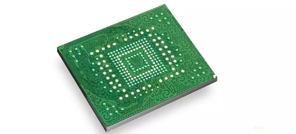
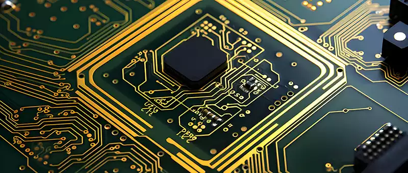
PCB as an important part of electronic equipment, its quality and reliability requirements are increasing. pcb testing is a complex and critical link, involving the application of a variety of technologies and pcb testing methods, but also need to consider a number of factors in the design process.
7 PCB Testing Techniques
- Flying probe test
PCB bare board and assembled board can be flying probe test, either passive mode or active mode.
Flying probe test utilizes special probes to check the test points, which can include resistance, capacitance, inductance, no holes through the holes or components of the termination. It not only detects the value of unenergized components, open or short circuits, but also measures voltages and checks the position of diodes and transistors.
Advantages of flying probe testing:
Relatively low cost
Wide test coverage
No fixtures required
Quick to implement
Disadvantages of flying probe testing:
Time-consuming process as the probe needs to be moved between several measurement points
Difficult to set up if the board does not have pre-determined test points, test vias or mask vias
Only one-time testing of capacitors connected in parallel is possible.
- ICT Testing
ICT testing uses pre-installed electronic probes that are aligned with the underside of the board through preset access points to establish an accurate and stable electrical connection. The test probes cause current to flow at predetermined design test points.
ICT is capable of detecting short or open circuits, defective soldermasks, and misplaced or missing components. This method involves the use of test fixtures to properly secure the board with the probes and the use of test fixtures to check multiple components on the pcb board at the same time. This method of testing helps save time.
Advantages of ICT testing:
Suitable for high volume production
Up to 90% test coverage
Accurate test results
Avoids human errors
Disadvantages of ICT Testing:
Not suitable for small batch production
Unable to detect gaps or insufficient soldermasks
Higher cost
The use of test fixtures and other techniques increases the cost.
- FCT Testing
FCT testing is used for quality control and to ensure that the device operates as intended. Test parameters are provided by the customer or designer based on the design.
This technique usually consists of simple switching tests and sometimes requires complex software and precise protocols. Functional testing directly checks the functional performance of the board under real environmental conditions.
Advantages of FCT testing:
Low cost
Wide range of applications, customizable to the design
Does not affect the life of the board compared to other tests that apply too much stress
Disadvantages of FCT testing:
Requires experienced technicians to operate
- AOI Testing
AOI testing uses 2D or 3D cameras to capture high-resolution images and verify that these images are consistent with the schematic. It also compares it with perfect and imperfect designs stored in a database to identify all visible errors very accurately.
AOI testing is often used in conjunction with other test methods to ensure the accuracy of the test results, for example with flying probe testing or in-circuit testing.
AOI testing can be integrated directly into the production line and is used to prevent premature board failures.
Advantages of AOI testing:
Ability to accurately detect fatal defects
Consistent approach to testing
Disadvantages of AOI testing:
Can only detect surface defects
The testing process is relatively time consuming
Test setup may vary depending on the design
Database based testing is not always 100% accurate
- Aging Test
Aging testing is a method of early inspection of circuit boards to prevent dangerous failures that may occur after manufacturing is complete. This method effectively detects a board’s maximum operating rating by triggering a failure by exceeding specified operating limits.
Aging testing involves a wide range of operating conditions, including voltage, current, temperature, operating frequency, power, and other design-related factors.
Benefits of Aging Test:
Increase product reliability
Verifies the functional performance of the board under environmental conditions
Disadvantages of Aging Test:
Test stresses beyond the rated values may shorten the life of the boards.
The process requires more time and effort
- X-ray Testing
X-ray testing utilizes X-ray imaging to detect errors in hidden components, solder connections, BGA packages, internal alignments and barrels in circuit boards.
Advantages of X-ray testing:
No need to inspect the PCB layer by layer
X-ray machines can easily inspect internal layers from the top of the circuit board.
Disadvantages of X-ray testing:
Requires experienced and skilled technicians to operate
Testing process requires more labor and cost
- Manual Visual Inspection
Manual visual inspection is an inspection method performed by a technician using the naked eye or a magnifying glass. This method identifies undisclosed component alignments, missing components, and other defects.
Advantages of Manual Visual Inspection:
Simple and basic method
Disadvantages of Manual Visual Inspection:
Vulnerable to human error
Unable to detect small and invisible defects
9 PCB testing methods
- Bezel Edge Width
It is vital to maintain sufficient unoccupied space on opposite edges of the board to help perfectly secure the tester. Clear edges are key to achieving this goal. - Reference Points
The machine needs clear reference points to determine the exact position of the probes. These reference points (often referred to as datum points) are either located in the waste area of the panel or directly on the PCB substrate if the waste has been removed. Recommended datum locations are usually the upper left and lower right corners of the board. - Vias
In circuit board design, vias do not need to be covered in order to place test probes at their edge locations. - Component Pins
For good soldering results, it is often recommended that test probes be placed near component pins, although it is not necessary to test the component pins themselves during actual testing. By pushing the component pins to the pads, it is possible to connect the test points and avoid potential open-circuit problems. - Size
If the design has a large PCB size, it is recommended that the test access points be set as close together as possible to improve test efficiency. - Cleanliness
Ensuring that the assembly is clean is essential to remove unwanted flux. Sometimes the tester may need to move the probe position to get better access, and unnecessary flux residue may cause failures and increase test time. - Probing Points
Introduce easily accessible probe points in the bottom ground and power rails of the PCB, especially for those sides that are not probed. This can speed up the short circuit test process by allowing fixed probes to be used as temporary fixtures and help reduce overall test time and cost. - Test Access
If conditions permit, try to concentrate test access points on one side of the component assembly to ensure that there is at least one available test point for each network. If a double-sided test machine is used, flipping the board to test the other side will increase costs. - Component Height
There are maximum component height limits allowed in both the probed and undetected areas of the PCB, usually around 40mm and 90mm respectively. If it is necessary to install high components in undetected or detected areas after testing, it is recommended that they be placed at the bottom of the PCB. Tall components may create no-fly zones in certain areas or hinder the ease of test access.
For PCB testing methods, several factors need to be taken into consideration during the design process to ensure smooth testing. From the selection of datum points to component height limits, every detail may affect the final test results. Therefore, at the beginning of the PCB design, should take into full account the needs of the test, and make corresponding adjustments and optimization in the design process. This will not only improve the efficiency of the test, reduce test costs, but also ensure product quality and reliability.