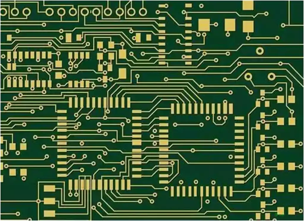
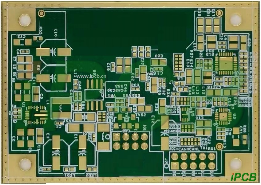
HDI pcb (High Density Interconnector), that is, high-density interconnect board, is the use of micro-blind buried hole technology of a line distribution density is relatively high circuit boards. HDI boards have an inner layer of lines and outer layer of lines, and then the use of drilling holes, holes, such as metallization and other processes, so that each layer of the line to achieve the internal connection.
HDI boards are generally manufactured using the layer-by-layer method, and the more layers there are, the higher the technical grade of the board. Ordinary HDI board is basically 1 time layer, high-level HDI using two or more times the layer technology, while the use of stacked holes, plating to fill the holes, laser direct hole punching and other advanced PCB technology.
When the density of PCB increases more than eight layers of boards, to HDI to manufacture, its cost will be lower than the traditional complex compression process. HDI boards are conducive to the use of advanced assembly technology, its electrical performance and signal correctness is higher than the traditional PCB. In addition, HDI boards offer better improvements in RFI, EMI, ESD, and thermal conduction.
Are all PCBs with blind via called HDI boards?
HDI boards are high-density interconnect boards, blind hole plating and then the second compression of the board are HDI boards, divided into first-order, second-order, third-order, fourth-order, fifth-order HDI, such as the iPhone 6 motherboard is a fifth-order HDI. simply buried holes are not necessarily HDI.
The difference between HDI and blind via PCB
HDI is smaller and lighter
HDI boards are made of traditional double-sided boards as core boards, which are laminated by constant accumulation of layers. This type of circuit boards made by continuous layering is also called Build-up Multilayer (BUM). Compared to conventional circuit boards, HDI circuit boards are “light, thin, short, and small”.
HDI electrical interconnections between the layers of the board is through the conductive through-hole, buried holes and blind holes connected to the realization of its structure is different from the ordinary multilayer circuit boards, HDI boards in a large number of micro-embedded blind holes. HDI laser direct drilling, while the standard PCB is usually used to mechanically drill the holes, so the number of layers and the aspect ratio tends to be reduced.
HDI motherboard production process
HDI board high-density is mainly reflected in the hole, line, pad density, interlayer thickness of these points.
● Micro-conductor holes: HDI boards contain blind holes and other micro-conductor hole design,which is mainly manifested in the aperture diameter of less than 150um micro-hole into the hole technology and cost,production efficiency and precision control of holes and other aspects of the high requirements of the chemical. Conventional multilayer circuit boards only have through holes and no tiny buried blind via.
● line width and line spacing refinement: its main performance in the wire defects and wire surface roughness requirements are becoming more and more stringent. General line width and line spacing does not exceed 76.2um.
● High pad density: the density of welded joints per square centimeter is more than 50.
● Thin dielectric thickness: This is mainly manifested in the interlayer dielectric thickness to 80um and below, and the thickness uniformity requirements are becoming more and more stringent, especially for the characteristic impedance control of high-density boards and packaging substrates.
Better electrical properties of HDI boards
HDI not only enables end-product designs to be more miniaturized, but also meets higher standards of electronic performance and efficiency.
HDI’s increased interconnect density allows for enhanced signal strength and improved reliability. In addition, HDI boards offer better improvements in RFI, EMI, electrostatic discharge, heat transfer, etc.HDI also utilizes full digital signal process control (DSP) technology and a number of patented technologies to provide full-range adaptability to loads and strong short-term overload capability.
HDI boards have very high requirements for buried hole plugging
As can be seen from the above, whether it is the volume of the board, or electrical performance, HDI are better than ordinary PCB a chip. Where there are two sides of the coin, HDI’s other side is as a high-end PCB manufacturing, its manufacturing threshold and process difficulty are much higher than ordinary PCB, production should pay attention to more problems – especially buried holes plug holes.
Currently HDI manufacturing core pain points and difficulties is buried holes plug holes. If the HDI buried holes plug holes are not done properly, there will be major quality problems, including uneven board edges, uneven media thickness, pads have pits and so on.
The board surface is not flat, the line is not straight in the depression caused by the beach phenomenon, which will cause the line gap, broken line and other defects
Characteristic impedance also fluctuates due to uneven dielectric thickness, resulting in unstable signals.
Unevenness of the pads can lead to poor quality of the subsequent package, resulting in the loss of electronic components.

How to differentiate between first-order, second-order and third-order HDI PCBs?
The first order is relatively simple, the process and technology are well controlled.
Second-order will begin to trouble, a problem of alignment, a hole and copper plating. There are many kinds of second-order design, one is the staggered position of each order, need to connect the next neighboring layer through the wire in the middle layer, the practice is equivalent to two first-order HDI, the second is, two first-order holes overlap, through the superposition of the way to achieve the second-order, the process is similar to the two first-order, but there are a lot of process points to be specially controlled, that is, the above mentioned. The third is directly from the outer layer of holes to the third layer (or N-2 layer), the process is much different from the previous, the difficulty of punching holes is also greater.
For the third order of the second order of analogy that is.
Examples are as follows:
6-layer board in the first order, the second order is for the need to laser drill holes in the board, that is, refers to the HDI board.
6 layers of first-order HDI board refers to blind holes: 1-2, 2-5, 5-6. That is, 1-2, 5-6 need laser drilling.
6 layers of second order HDI board means blind holes: 1-2,2-3,3-4,4-5,5-6. i.e. 2 laser drilling is required. First drill 3-4 buried holes, then press fit 2-5, then first drill 2-3, 4-5 laser holes, then press fit 1-6 for the second time, then drill 1-2, 5-6 laser holes for the second time. Finally the through holes are drilled. This shows that the second order HDI boards have been pressed twice and laser drilled twice.
In addition, the second-order HDI plate is also divided into: wrong hole second-order HDI plate and stacked hole second-order HDI plate, wrong hole second-order HDI plate refers to the blind holes 1-2 and 2-3 are staggered, while the stacked hole second-order HDI plate refers to the blind holes 1-2 and 2-3 are stacked together, for example: blind: 1-3, 3-4, 4-6.
And so on third order, fourth order …… are the same.
Electronic products are constantly moving towards high-density, high-precision development, the so-called “high”, in addition to improving machine performance, but also to reduce the size of the machine. High-density integration (HDI) technology can make the end product design more miniaturized, while meeting the higher standards of electronic performance and efficiency. Currently popular electronic products, such as cell phones, digital (camera) cameras, notebook computers, automotive electronics, many of which use HDI boards. With the upgrading of electronic products and market demand, the development of HDI pcb will be very rapid.


