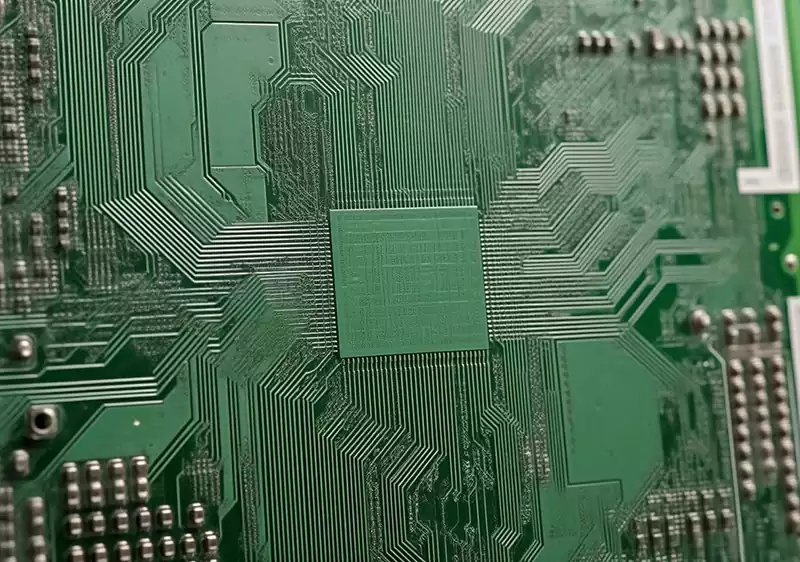
Milling PCB board is a method of processing printed circuit boards (PCBs) using CNC milling technology. It cuts and repairs PCB boards through milling methods to form the final form of the product. With the booming of the electronics market, the demand for PCB milling technology is getting higher and higher.
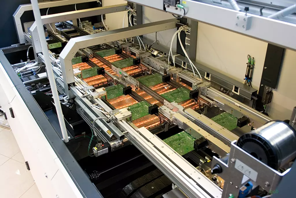
Reasons affecting the accuracy of the milling cutter depaneling machine cutting circuit boards
- equipment stability
The stability of the milling cutter depaneling machine has an important impact on the cutting accuracy. If the equipment is not stable enough, it may cause vibration or jitter during the cutting process, thus affecting the accuracy of cutting PCB.
Solution: Before using the milling cutter depaneler, make sure that the machine is stable and balanced on a horizontal plane. Check that the fixing screws are not loose to ensure that the machine can maintain a stable cutting condition. Also, make sure there are no impurities between the milling cutter and the cutting area to minimize inertial jitter during the cutting process.
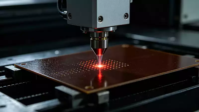
- Cutter wear
The degree of tool wear directly affects the accuracy of cutting. When the cutter is worn, the depth and angle of the cut board may change, thus affecting the cutting accuracy.
Solution: Check the tool wear regularly and replace the tool according to the degree of wear. In addition, make sure the tool is installed correctly and adjust the position and angle of the tool to ensure the cutting accuracy.
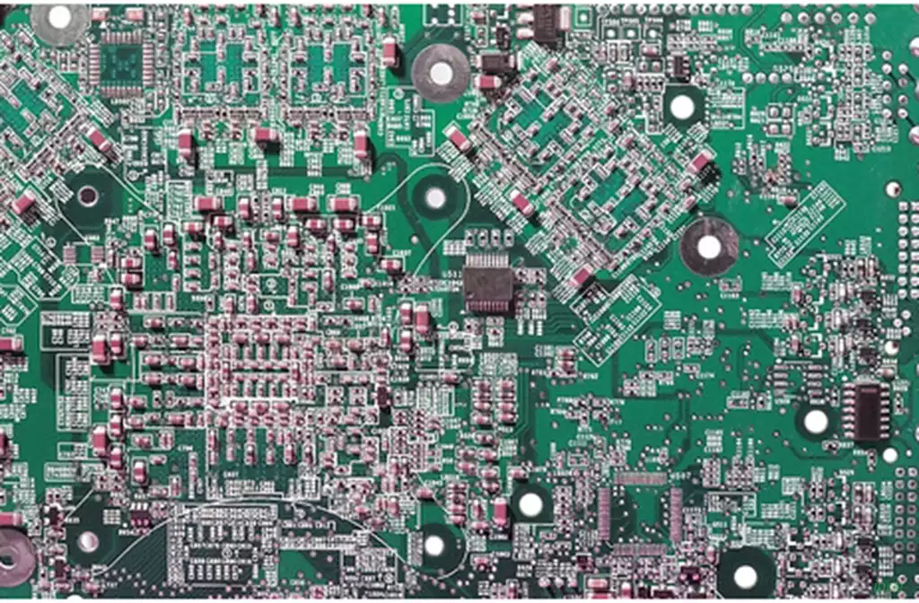
- Material selection and preparation
The material properties of PCB boards also have a certain impact on the cutting accuracy. If the thickness, hardness or weight distribution of the material is not uniform, the cutting may produce offset or uneven cutting.
Solution: Before using the milling cutter depaneling machine, select uniform PCB boards and process them appropriately. For example, check the thickness uniformity of the board, remove defects that may cause offset. Ensure that the quality and size of the board to be cut meets the requirements.
- Improper parameter setting
Incorrect setting of the cutting parameters of the milling cutter depaneling machine will also affect the accuracy of the cut. This includes cutting speed, feed rate, depth of cut, etc.
Solution: Before using the milling cutter depaneling machine, according to different Printed circuit boards and cutting requirements, the correct parameter settings. Adjust the cutting speed and feed speed, as well as the cutting depth, according to the characteristics and requirements of the cut material to maintain the accuracy of the cut.
The milling technology of pcb CNC milling machine includes the selection of the direction of travel, compensation methods, positioning methods, the structure of the frame, and the point of the lower tool. All are important aspects to ensure the milling process.
Tool travel direction, compensation method:
When the milling cutter cuts into the plate, one of the cut surface is always facing the cutting edge of the milling cutter, and the other side is always against the cutting edge of the milling cutter. In the former case, the machined surface is smooth and has high dimensions. The spindle always rotates clockwise. So whether the spindle fixed table movement or table fixed spindle movement of CNC milling machine, in milling the external contour of the printed board, to use the counterclockwise direction of the tool. This is often referred to as reverse milling. And in the PCB board internal milling frame or slot using the smooth milling method. Milling board compensation is in the milling board when the machine tool is automatically set according to the set value so that the milling cutter automatically milling line to the center of the milling cutter diameter offset set by half, that is, the radius distance, so that the milling profile and program settings to maintain consistency. At the same time, if the machine has the function of compensation must pay attention to the direction of compensation and the use of program commands, such as the use of compensation commands will make the shape of the circuit board more or less equivalent to the diameter of the milling cutter length and width of the dimensions.
Positioning methods and lower cutter point:
Positioning methods can be categorized into two; one is internal positioning and the other is external positioning. Positioning is also very important for process development personnel, generally in the PCB substrate pre-production should determine the positioning of the program.
Internal positioning is a common method. The so-called internal positioning is to choose the PCB printed circuit board mounting holes, insertion holes or other non-metallized holes as positioning holes. The relative position of the holes strive to be on the diagonal and as far as possible to select a large diameter holes. Metallized holes cannot be used. Because the difference in the thickness of the plating in the hole will affect the consistency of your selected positioning holes, while taking the board is easy to cause damage to the plating in the hole and the edge of the hole surface, in order to ensure that the PCB printed circuit board positioning under the conditions of the number of pins, the smaller the better. General small board using 2 pins, large board using 3 pins, the advantages are accurate positioning, board shape deformation small degree of high profile, milling and cutting speed. The disadvantages of the board a variety of aperture types need to prepare a variety of diameters of the pins, such as the board does not have available positioning holes, in advance of the production of the need to discuss with customers in the board to add positioning holes more, more cumbersome. At the same time each kind of board milling template different management is more troublesome, higher costs.
External positioning is another positioning method, is used in the board external positioning holes as milling board positioning holes. The advantage is that it is easy to manage, if the first production specification is good, the milling plate template is generally about fifteen kinds. As a result of the use of external positioning so can not be milled down the board, otherwise the board is very easy to damage, especially splicing board, due to the milling cutter and vacuum device will bring the board out of the PCB board damage and milling cutter breakage. And the use of segmented milling to leave a combination of methods, the first milling board when the milling board after the completion of the program pause and then the board fixed with tape, the implementation of the second section of the program, the use of 3mm to 4mm drill will be combined with the drilling off. The advantage is that the template is less costly and easy to manage, can mill all the board without mounting holes and positioning holes in the circuit board, small craftsmen management is convenient, especially CAM and other advance production staff can be simplified, while optimizing the utilization of substrates. The disadvantage is that due to the use of drills, the circuit board shape left at least 2-3 raised points is not beautiful, may not meet customer requirements, milling time is long, the labor intensity of workers is slightly larger.
Frame and lower knife point:
The production of the frame belongs to the PCB circuit board prior to the production, frame design not only has an impact on the uniformity of plating, at the same time also has an impact on the milling board, such as the design of the frame is easy to deform or in the milling board to produce some of the small block loaded with a small piece of waste, resulting in the waste block will clog the dust pipe or touch off the high-speed rotation of the milling cutter, the deformation of the frame, especially for the external positioning of milling boards caused by the finished product board deformation, and other lower cutter point and the order of machining Choose well, can make the frame to maintain the strength of the fast speed. Choose not good, the frame is easy to deform and make the printed board scrap.
Milling process parameters:
Milling with carbide milling cutter PCB printed board shape, milling cutter cutting speed is generally 180 ~ 270m/min. Calculation formula is as follows (for reference only):
S = pdn/1000 (m/min)
Where: p: PI (3.1415927)
d: milling cutter diameter, mm
n; milling cutter speed, r/min
Enhancement of milling PCB board process needs to start from the equipment, tools, materials, parameters and milling technology and other aspects to ensure that accuracy and efficiency. With technological innovation, PCB milling process is expected to usher in a more intelligent and efficient future.