PCB backdrill, also known as controlled depth drilling, is simply the process of drilling a hole from the back side of an already manufactured multilayer circuit board. However, this is not just playing, but to accurately trim some of the through-holes (we also call it PTH holes, that is, plated through-holes) in those unwanted ‘little tail’ – we call it ‘stubs! stubs’. These stubs, like the circuit board on the excess burden, although it seems inconspicuous, but in high-speed signal transmission is a big trouble.
In a multilayer PCB, through-holes are like bridges connecting different layers of circuitry, running the entire board and allowing current and signals to flow freely between the layers. But sometimes these holes are punched too deep, leaving a section of useless stubs. These stubs are like tiny antennae when high-speed signals are being transmitted, absorbing and reflecting signals, making them unclear and increasing interference, which affects how well the whole circuit works.
In order to deal with this problem, engineers came up with the idea of backdrill. It is like a highly skilled ‘scissors’, specifically responsible for trimming off these excess ‘tail’, so that the signal transmission is smoother, no obstruction.
PCB backdrill process
Seal locating holes with dry film before plating.
Plate holes with copper to create conductive paths.
Create outer layer graphics on plated PCB.
After the outer layer graphics are created, the graphics are plated on the PCB. Prior to this process, it is important to seal the locating holes with dry film.
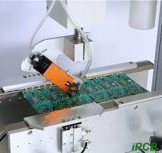
Backdrill is done using the locating holes from the initial drilling process to align the holes and using a drill bit to back drill the plated holes that require this process.
After backdrill, the board needs to be cleaned to remove any residual drill chips that may be present in the back drilling.
The board is inspected to verify that the backdrill process was performed accurately and that signal integrity was enhanced.
According to the different processes, backdrill can be divided into several types, such as two-drill back drilling, positive piece graphic plating back drilling, and one-time plating sufficient back drilling.
Two-drill back-drilling, which achieves the effect of back-drilling by precisely controlling the depth of the drilled holes, is usually applied to those occasions where the back-drilled holes do not need to be filled and where there is no strict control over the burrs (phi) produced by back-drilling. The advantage of this method is that the process is relatively simple, but the disadvantage is also obvious, that is, the burrs generated by back drilling cannot be effectively dealt with, and the length and alignment of the stub are also difficult to control accurately.
Backdrill after plating is a widely used and technically mature back drilling method. Its advantage lies in the ability to effectively remove the burrs generated in the process of back drilling, but the disadvantage is that it is easy to scratch the tin layer in the operation process, resulting in open circuits after etching, especially for the holes with aspect ratios greater than 10:1, which is prone to poor tin plating, while the copper layer of the wall of the holes in the etching process may also be occluded.
Backdrill after surface plating and back drilling after copper-tin plating of the whole board are both applicable to the process of ‘back drilling + POFV (a special process)’, but there are differences in the processing flow and the treatment of back drilling burrs.
The flash copper-tin plated back drilling method is mainly used for micro-hole back drilling of through-holes with a diameter of less than 0.2 mm. Its advantage lies in the ability to effectively deal with various back drilling process burrs, greatly reducing the probability of residue clogging holes, but the disadvantage lies in the processing process is relatively long, and the tin-plating process is more demanding.
Strategies for PCB backdrill to address signal integrity challenges
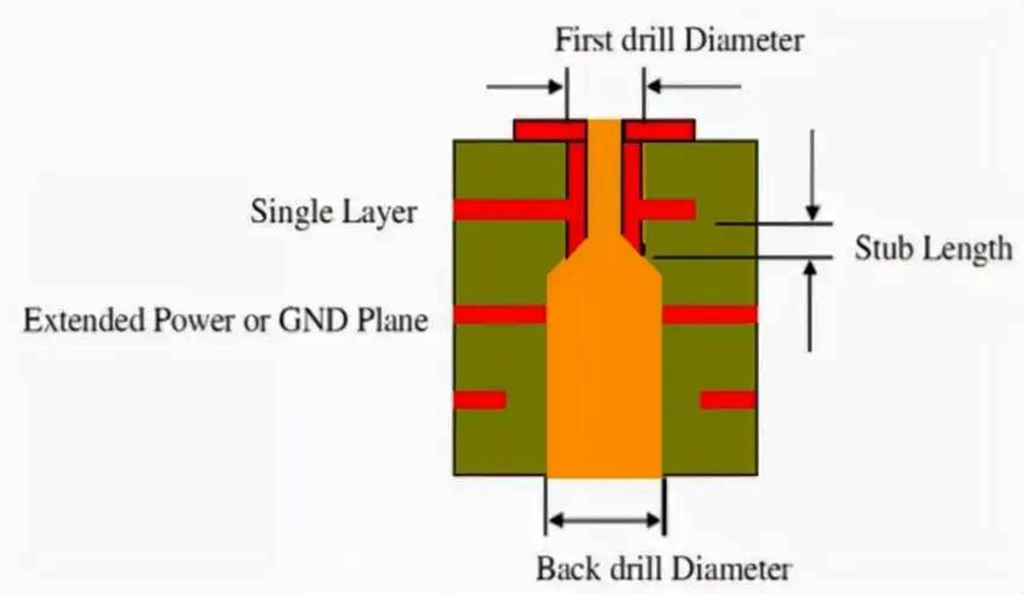
After the plated through holes are manufactured, we can re-drill the holes using a slightly larger drill bit to accurately remove those excess stubs. In this process, the holes are back-drilled to a predetermined and controlled depth that is close to, but does not touch, the last layer used for the hole.
Ideally the stubs should be less than 10 mils in length, and it is worth noting that the diameter of the back-drilled holes will be larger than the diameter of the plated through-hole, typically the diameter of the drill bit used for back-drilling will be between 8 mils and 10 mils larger than the diameter of the original drill bit, this is because the gaps between the alignments and planes have to be sufficiently generous to avoid accidentally drilling through the alignments and planes that are adjacent to the back-drilled holes during the back-drilling process.
Advantages and Disadvantages of PCB Backdrill.
Advantage:
Backdrill technology significantly reduces signal attenuation and ensures stronger, more reliable signal transmission. It also minimises interference with impedance matching caused by stubs, which in turn reduces EMI/EMC emissions.
Backdrill is an effective means of combating signal distortion. Since through-hole stubs cause deterministic jitter, which usually originates from signal crosstalk, EMI and noise, removing these stubs removes the source of deterministic jitter, improves signal quality and prevents signal distortion.
Backdrill helps to reduce crosstalk between vias and reduces deterministic jitter in the signal, thereby lowering the overall bit error rate (BER) of the signal.
It also reduces the excitation of resonant modes, minimises the use of buried and blind vias, and simplifies the PCB production process while minimising the impact on design and layout.
Backdrill also extends channel bandwidth and is more cost effective than sequential lamination.
Disadvantages:
Back-drilling technology is primarily suited for high-frequency boards in the frequency range of 1 GHz to 3 GHz where blind vias cannot be used. In addition, special techniques must be used to ensure that no damage is caused to the traces and planes transverse to the holes in the backplane.
Challenges of the back drilling process
Accurate management of backdrilling depth: Backdrilling technology relies on the depth control capability of the drill bit to create blind holes, the accuracy of which is mainly affected by the accuracy of the backdrilling equipment itself and by small variations in the thickness of the media. In addition, external factors such as the resistance to which the drill is subjected, the angular design of the drill tip, the state of contact between the cover plate and the measuring system, as well as the warping and deformation of the plate may have an unfavourable effect on the depth accuracy of the backdrill. Therefore, in production practice, drilling materials must be carefully selected and appropriate drilling strategies must be adopted to ensure the accuracy of the back-drilling depth to achieve the best possible production results.
Strict control of backdrill accuracy: The back-drilling process is a secondary drilling process based on the primary drilling, so the accuracy of the secondary drilling is critical. Factors such as the slight rise and fall of the board due to temperature and humidity changes, the level of precision of the equipment, and the drilling strategy adopted may all have an impact on the degree of overlap between the secondary drilling and the primary drilling, which is extremely critical to the quality control of the PCB in the subsequent processing.
As an important process in modern electronics manufacturing, PCB backdrill technology effectively solves the key problem of signal integrity in multilayer circuit boards by virtue of its unique ability to drill holes at a controlled depth. However, the back-drilling process also faces the challenges of precise depth management and strict control of accuracy. This requires us to use high-precision equipment, optimised drilling materials and strategies to ensure the accuracy and stability of back drilling during the production process. At the same time, choosing the right type and method of back drilling for different application scenarios and needs is also key to achieving the best production results.
