In the field of electronic engineering technology, breadboard vs pcb is two widely used tools in different stages of circuit design and development. Breadboards serve as a recyclable platform for building and testing electronic circuits without soldering. Its structure consists of a grid of interconnected holes that allow for the quick insertion, removal and relocation of components and wires. Breadboards are ideal for the initial design and experimentation stages of a circuit because they allow designers to easily make modifications and troubleshoot problems. In contrast, printed circuit boards (PCBs) are a more permanent and stable solution for circuit design, in which components are soldered to a board surface that has been etched with conductive tracks. These tracks are responsible for connecting the components to form a reliable and durable circuit, and PCBs are often used in final products or prototypes where performance and stability are critical.
Breadboards are experimental tools used to build basic circuit prototypes.Initially,circuit connections were made on wooden boards that resembled cut-out bread, but as technology progressed, by the 1970s plug-in circuit boards (also known as array boards), which did not require soldering, became popular, and the term breadboard came to be used as a generic term for these plug-in boards, which facilitated the prototyping of circuits. Therefore, in English, ‘breadboard’ and ‘prototype’ can be regarded as synonymous in a sense. Because they require no soldering and are reusable,breadboards are essential for prototyping circuits in schools and laboratories.
Flexibility and limitations of breadboard prototyping:
Early in development, breadboard shows great value by supporting rapid prototyping, enabling designers to test configurations and ideas without soldering. This flexibility is especially valuable for teaching purposes, small projects,or when component performance is not yet clear. This flexibility is especially important when multiple solutions need to be tested, the component meets the design requirements,the solution to a particular problem is uncertain, or the component is unfamiliar and further testing is required.
However, breadboards have some limitations:
Connection stability: temporary connections on breadboards may loosen or make intermittent contact, leading to unstable circuit behaviour. This can add complexity to debugging, especially in complex circuits.
Signal Quality: Breadboards are not suitable for high frequency circuits or circuits where signal integrity needs to be ensured.Their parasitic capacitance and inductance may interfere with the signal and cause performance problems.
Limited scalability: As project complexity increases, the physical size and wiring of breadboards can become large and unwieldy,making them more difficult to manage and troubleshoot.
Breadboard construction features:
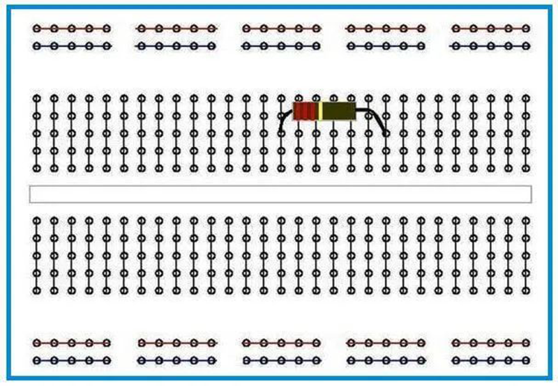
The centre of the breadboard is provided with a dividing slot which clearly divides the breadboard into upper and lower zones.In each column of each region, the five jacks in the upper half are connected to each other and the five jacks in the lower half are similarly connected to each other,but there is no conductive connection between the upper and lower regions.In addition,the top and bottom edges of the breadboard are provided with two rows of jacks for connecting the positive and negative poles of the power supply,and these two rows of jacks are each internally connected to each other,providing a convenient means of accessing and grounding the power supply for the circuit.
When wiring the breadboard,the following basic principles should be followed:
- Minimise the number of connection points;
- Try to avoid the formation of cross-links (i.e., the ‘overpass’ phenomenon);
- Ensure the stability of the connection;
- To facilitate test operations;
- The layout should be as compact as possible;
- The layout should be as consistent or similar to the schematic diagram as possible;
- The use of power supply areas should be clear and unambiguous.

PCB Prototyping Superiority: Advantages over Breadboards
While breadboards excel in the initial testing phase, moving to PCB prototyping brings a number of significant advantages:
Robustness: PCBs provide stable and durable circuit connections. By soldering components in place, PCBs eliminate the problem of loose connections that are common on breadboards. This robustness is critical for any project that moves beyond the prototype stage and into real-world applications.
Signal Quality: The PCB’s design incorporates precise conductive paths that minimise interference from parasitic components, thus ensuring accurate signal transmission. This feature makes PCBs the preferred solution for high-frequency circuits and performance-critical designs.
Compact Layout: PCBs allow designers to achieve a more compact and organised circuit layout. Components can be arranged more closely together, and multi-layer PCB technology allows complex circuits to fit into a smaller space, which is essential for the compact design of modern electronic devices.
Professional image: The use of PCBs not only improves the reliability and performance of a project, it also gives it a more professional appearance. PCBs are an indispensable standard choice for any project planned for commercial production.
Expansion Flexibility: PCB prototyping offers excellent expandability, allowing designers to expand circuits by adding connectors or jumpers. This feature allows designers to easily add and test new solutions without having to make extensive changes to the entire board. Common connector types such as M.2 (PCIe), Stemma, Arduino, Raspberry Pi, mikroBUS, and Qwiic facilitate the integration of a wide range of modules and peripherals, further promoting modularity and future-proof compatibility of designs.
In the practice of circuit design and development, breadboard vs PCB each demonstrate their unique value.With its rapid prototyping and ease of modification, the breadboard has become the tool of choice for the preliminary design and experimental phases of circuits,and is particularly suited to scenarios such as teaching purposes, small-scale projects, or component performance testing. It allows designers to quickly build circuits for initial verification and troubleshooting without soldering, greatly improving design efficiency.
However, as the project progresses and circuit complexity increases,the superiority of PCB comes to the fore. Its stable connection, good signal quality, compact layout, and professional appearance make PCBs more suitable for final products or prototyping with high performance and stability requirements.PCBs are not only able to meet the needs of complex circuits, but also improve the reliability and maintainability of the circuits through multi-layer design and modular layout.
Therefore, breadboard vs PCB each has its own application scenarios and advantages in the circuit design and development process.Designers should reasonably choose to use breadboards or PCBs for circuit design and production according to the specific needs of the project,the development stage,and the cost budget and other factors. The two complement each other and together provide strong support for the development of the field of electronic engineering. In practical application, designers should use these two tools flexibly to achieve the design and development goals of the circuit in an optimal way.


