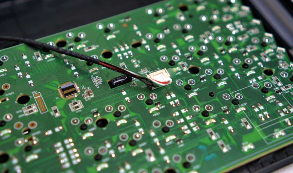
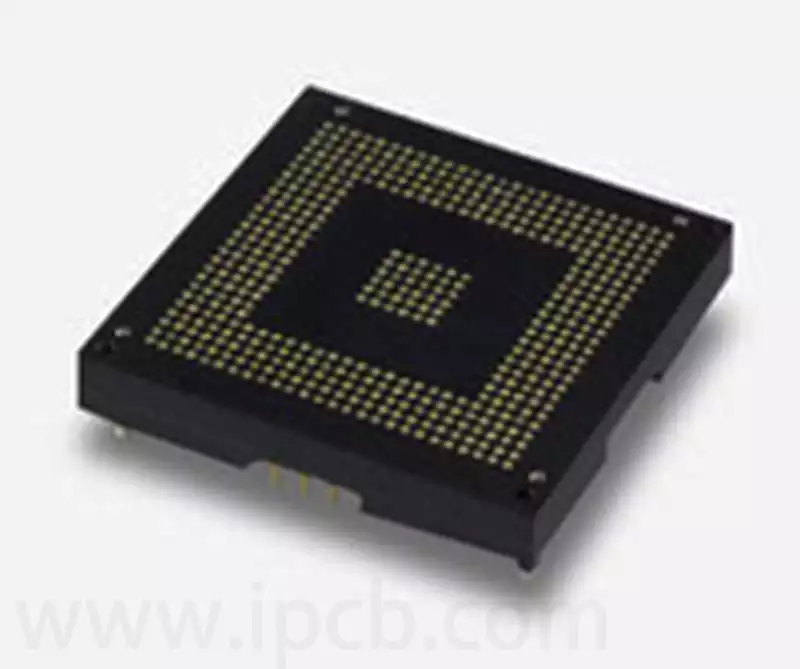
The ball grid array socket is an adapter that allows for pluggable mounting without directly soldering BGA-packaged integrated circuits (ICs) to the test substrate. By connecting the solder balls of the IC to the pads of the test substrate via the BGA socket, the risk of poor contact (e.g. open or short circuit) and IC damage is effectively reduced. At the same time, this approach makes the evaluation process faster and more flexible.
Especially in the functional verification stage of ICs, ball grid array socket make it easy to compare the performance and operating conditions of new chips, analyse faults and program operations, which significantly improves the efficiency of prototype development. In addition, in test environments where ICs need to be replaced frequently, BGA sockets have the advantage of reducing the labour intensity and risk associated with repetitive soldering.
However, the complex structure and relatively high cost of ball grid array socket, coupled with the larger substrate space they require, make them unsuitable for large-scale use on mass production lines. Nevertheless, ball grid array sockets are still an indispensable and critical tool in IC testing during the development phase.
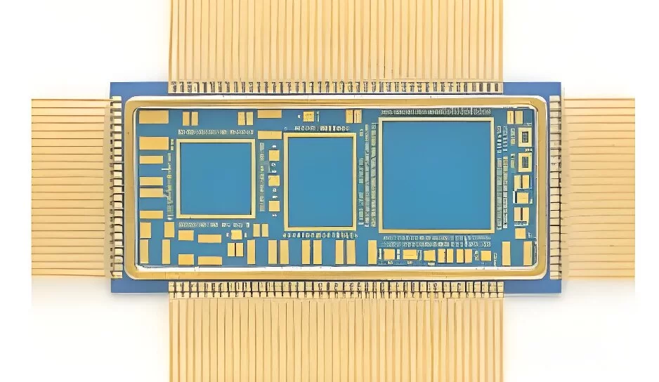
Ball grid array socketare widely used in computers, communication devices and consumer electronics. It is widely used in microprocessors, GPUs, FPGAs, and other high-performance integrated circuits.BGA aging test socket is a necessary test device for aging test of BGA series packages. When it is necessary to test the functionality of the BGA chip, the BGA chip to be tested can be inserted into the slot of the substrate, and the socket can be connected to the test system for testing through physical connection. In recent years, with the development of microelectronics packaging technology and high-speed signal transmission requirements, the ball grid array socket is increasingly widely used.
Designing for manufacturability
Taking the ball grid array socket system into account at an early stage of product design not only optimises the performance of the board, but also makes it easier for production engineers to review the design at an early stage to ensure its manufacturability. For example, in the reflow soldering process, where the size and weight of the socket affects the optimisation of the heating profile, a lightweight socket can help to achieve even heat distribution, thus simplifying the installation process and shortening the overall production cycle.
Surface mount sockets are typically connected to pads on a motherboard by end-face soldering. However, coplanarity differences between the board and the BGA device can lead to fluctuations in connection strength, shock resistance, and temperature cycling performance of the solder joints. By using sockets terminated with low-temperature eutectic solder balls, it is possible to form stronger solder joints than conventional pin-to-pad connections, thereby effectively addressing these issues. In addition, the sockets are assembled in a tape-and-reel (belt-and-wheel) format, which makes it possible to make full use of automated component placement equipment on the production line, further improving productivity.
Dimensional Considerations
Mounting BGA devices directly to a motherboard requires specific determination of the assembly dimensions, including the size and height of the contacts, and the space around the components required to ensure airflow and heat sink mounting. Device displacement and insertion are critical issues during the mounting process. Using sockets for BGA devices introduces additional dimensional considerations.
If an existing motherboard needs to be redesigned to accommodate a BGA device in socket form, the difference in size between the socket and the corresponding BGA device may result in increased time and cost to redesign the board to ensure that there is sufficient space around the BGA device that would otherwise not be available for the application. Similarly, if the post-installation socket causes the BGA device to be too tall and take up too much space, it may interfere with adequate airflow, heatsink mounting, and motherboard-to-chassis mounting. In this case, choosing a low-profile socket that is the same size as the BGA device contact points can minimise or eliminate board redesign efforts. These considerations should be taken into account early in the design process, and small, low-profile sockets are often the best choice when space is limited.
Electronics Considerations
As an electronic component, ball grid array socket should be installed with BGA devices in such a way as to minimise interference with the device signals. For low-speed devices, the electrical properties of the socket may have little effect on signal processing. However, for very high speed components, even the presence of the socket itself may alter the signal path enough to affect the signal or even the function of the component. In such cases, additional electronic components need to be considered during motherboard design to keep the signals on track. It is critical to consider these issues when routing a new board, as it is easier to determine component specifications and placement issues at an early stage of the design and can result in significant cost savings.
Mechanical Considerations
From a mechanical point of view, ball grid array socket , or socket adapter systems that carry BGA devices, present design challenges for both socket manufacturers and users. On the one hand, the socket connector must be strong enough to ensure that the BGA device is safe and stable and maintains good electrical contact with the motherboard. On the other hand, the mechanical forces applied need to be matched to the connecting devices within the socket or should be as low as possible when removing the device to prevent bending deformation or damage to the component and the motherboard.
The material and form of construction of the socket contacts are also extremely important. For example, a precision helical mechanical termination method using a copper-beryllium alloy with thicker gold plating on the internal contacts will provide better mechanical and electrical performance than a solution of the same material but with thinner gold plating. In addition, when testing sockets and devices, repeated insertion and removal of the adapter will eventually wear away the gold plating, altering the contact resistance and potentially causing bias in the test results. Therefore, it is clear that insufficient gold plating thickness will shorten the service life of the ball grid array socket, which means that frequent replacement with new sockets will be required.
Thermal Design Considerations
It is critical that the temperature characteristics of the socket (e.g., thermal resistance, temperature stability, coefficient of thermal expansion, and melting point) are matched to the BGA components to ensure good mechanical integrity and electrical performance throughout the temperature cycling cycle. If sockets are not properly matched to the BGA components, a number of issues can arise, such as affecting thermal design, reducing the mean time between failure (MTBF) of devices and motherboards, leading to frequent field returns, and inconsistencies between lab simulation performance and actual field application performance. For example, if the maximum operating temperature of the BGA package exceeds the maximum operating temperature of the plastics used in the sockets and adapters, distortion or melting may occur. If the coefficient of thermal expansion of the BGA device does not match that of the ball grid array socket and adapters, the motherboard or BGA may distort or create other localised distortion problems.
Cost Considerations
Adding any component to an electronic device involves a cost sacrifice. If the cost of the motherboard or BGA is low, flexibility can be used as needed. Being too specific about sockets may unnecessarily increase production and distribution costs with limited improvement in product performance.
However, in some cases, the rules for treatment are different. For example, when the board or BGA device is expensive; the development, test, simulation, and assembly processes need to be accelerated; and the BGA device needs to be field-programmed before it is mounted on the motherboard.
Ball grid array sockets are indispensable tools in the development and test of high-performance electronic devices. When designing and selecting BGA sockets, it is important to consider how best to match the overall system requirements to achieve stable, efficient operation and rapid iteration of high-performance electronics.