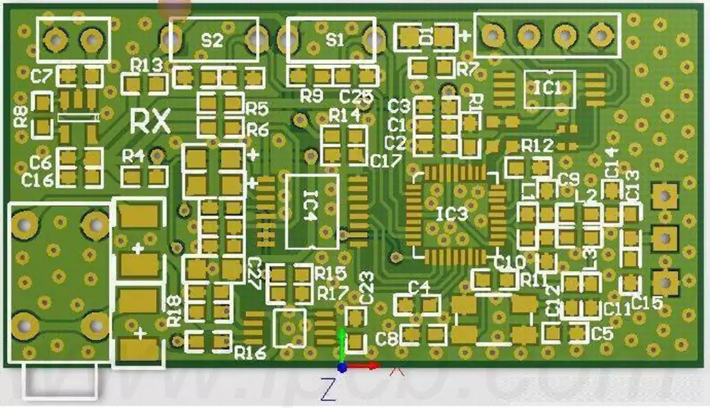
Microstrip patch antennas and their arrays may not be seen much but are the most widely used form of antenna. They are simple in structure and can be formed by a dielectric, a metal conductor patch on top of the dielectric, and a ground plane. Even the intervening dielectric can be an air structure. The more typical microstrip patch antenna is fabricated on a printed circuit board (PCB), using a photocopying method to etch the fine line structure on the conductive metal layer.
Since the PCB material is an important part of the microstrip patch antenna and its antenna array, the characteristics of the PCB material, including the type of conductive metal copper foil for the patch and ground, need to be carefully considered when designing the microstrip antenna. Also, the PCB manufacturing process can affect the performance of the microstrip patch antenna due to line tolerances; components of the PCB that may be additionally added to the manufacturing process (e.g., surface treatment plating) can also affect performance. Understanding how PCB materials work together and how they shape the final design requirements through the manufacturing process can help achieve the intended design purpose of a microstrip patch antenna or array, especially in the millimetre-wave band.
Since the PCB material is an important part of the microstrip patch antenna and its antenna array, the characteristics of the PCB material, including the type of conductive metal copper foil for the patch and ground, need to be carefully considered when designing the microstrip antenna. Also, the PCB manufacturing process can affect the performance of the microstrip patch antenna due to line tolerances; components of the PCB that may be additionally added to the manufacturing process (e.g., surface treatment plating) can also affect performance. Understanding how PCB materials work together and how they shape the final design requirements through the manufacturing process can help achieve the intended design purpose of a microstrip patch antenna or array, especially in the millimetre-wave band.
Impact of Dielectric Substrate Characteristics on Antenna Performance
The dielectric substrate of a microstrip patch antenna is one of the core components that determines its electromagnetic performance. The main influencing factors include:
- Dielectric constant (εᵣ): the higher the dielectric constant, the size of the antenna can be reduced (e.g., when εᵣ = 4.3, the patch length is about 1/2 √ εᵣ of the wavelength of the free space), but it will reduce the bandwidth (experiments have shown that the bandwidth of εᵣ increased from 2.2 to 10 may be reduced by more than 50%). Typical materials are e.g. FR4 (εᵣ ≈ 4.3), Rogers RT/duroid (εᵣ = 2.2-10.2).
- Substrate thickness (h): increased thickness improves bandwidth (e.g., bandwidth may be expanded by a factor of 2 when h is increased from 0.8 mm to 1.6 mm), but excessive thickness introduces surface wave losses and reduces radiation efficiency (IEEE experimental data show a ~15% drop in efficiency for h > λ₀/10).
Radiation Patch Design and Feeding Methods
- Patch Shape and Size:
- Rectangular patches are the most common form, with length L ≈ λ₀/2√εᵣ (λ₀ is the free-space wavelength) and width W affecting impedance matching (usually W/L = 1.5-2.0).
- Circular or toroidal patches can improve multi-frequency characteristics, e.g., the difference between inner and outer radii in dual-frequency designs needs to satisfy Δr ≈ 0.1λ₀.
- Feedthrough technology:
- Direct contact feeds (e.g., microstrip line feeds) are simple but have narrow bandwidths (2-5% typical);
- Electromagnetically coupled feeds (e.g., slit-coupled) extend the bandwidth to 10-15% (refer to Antenna Theory: Analysis and Design for data).
Environmental and Process Factors
- Temperature stability: Coefficient of Thermal Expansion (CTE) of the substrate leads to frequency drift, e.g. PTFE substrates have a frequency shift of about 0.1%/°C from -40°C to 85°C. 2. Process accuracy: Etching errors.
- Processing accuracy: Etching errors of ±0.1mm may result in a resonant frequency shift of 1-2% (based on measured results from IEEE Transactions on Antennas and Propagation).
When selecting PCB materials for microstrip patch antenna design, the effect of PCB material ‘composition’ should be considered. Material ‘ingredients’ such as the dielectric material itself, the type of metal copper foil, and the final surface coating affect the performance and characteristics of the antenna and circuit. For example, the dielectric constant of the dielectric material can affect the size of the patch (~ 1/2 of the wavelength), the thickness of the dielectric material also affects the electromagnetic (EM) field distribution of the antenna radiation.
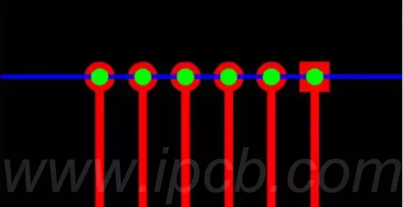
The radiation mechanism of a microstrip patch antenna is actually high-frequency EM leakage, where the rectangular patch passes through the longitudinal edges or ‘L’ direction of the leakage to generate the radiated EM field (the rectangular patch has no EM field in the width direction or ‘W’ direction). The final surface finish of the PCB has a significant effect on these EM fields radiating from the edge of the patch. For example, due to the conductivity of the final surface finish plating, the conductive properties of the PCB’s final conductor become complex and integrated. As an example, Electroless Nickel and Gold (ENIG) is a popular and proven final surface treatment that combines thick nickel with thin gold. However, nickel is a ferromagnetic material, on the one hand, in the copper foil conductor protection will also have magnetic loss; on the other hand, its conductivity is only 1/4 of copper, especially at higher frequencies will increase the conductor loss of the circuit and affect the phase response of the circuit. In microstrip patch antennas, the characteristics of ENIG will of course also affect the field strength generated by the microstrip patch antenna, especially at higher microwave and millimetre wave frequencies.
The choice of PCB conductor surface finish is a factor to be considered in microstrip patch antennas, as the surface plating alters the conductor losses at the patch edges. In the case of ENIGs, the conductivity at the conductor edges is a combination of copper, gold and nickel in varying proportions. There are many other PCB final surface coatings that can be done by chemical immersion processes such as chemically immersed tin or chemically immersed silver. The thickness of the plating obtained by this process is extremely thin and seems to vary less significantly across the circuit, but the effect on high frequency millimetre waves with small wavelength signals is not negligible.
The performance of microstrip patch antenna is affected by material properties, structural design and manufacturing process in many ways. Reasonable selection of dielectric substrate and surface treatment process, combined with accurate design and manufacturing, in order to achieve the ideal antenna performance.