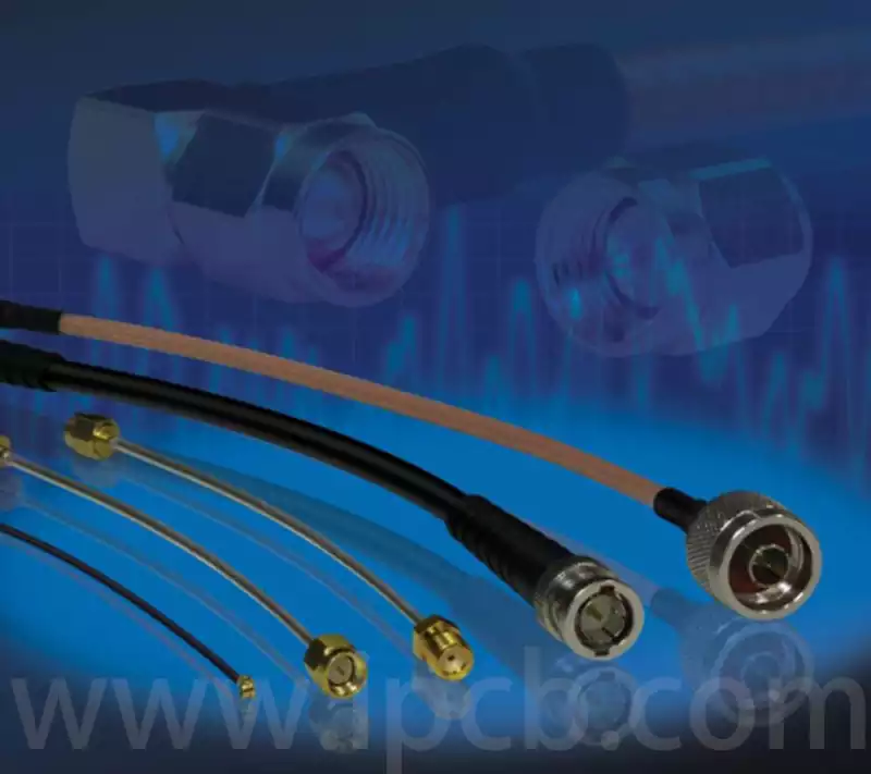
What is a RF cable? A RF cable is a type of cable used for transmitting high-frequency signals, and its construction differs from that of ordinary cables.
RF cable typically consist of the following four layers:
Inner conductor: A central metal wire (copper or silver-plated copper) responsible for signal transmission.
Insulation layer: A dielectric material (such as polyethylene or Teflon) that surrounds the inner conductor, providing insulation and securing it in place.
Outer conductor (shielding layer): A metal braided layer or foil layer that shields against external interference and forms a signal loop.
Outer jacket: Outer protective material (PVC, rubber) that resists wear, corrosion, and environmental changes.
Features of RF cable:
Can transmit a wide frequency band;
High resistance to external interference;
Low antenna effect and low radiation loss;
Simple structure, easy installation, and cost-effective.
Classification of RF Cables
RF cables come in a wide variety of types and can be categorized based on different criteria. By structure, they include coaxial, symmetrical, and spiral cables, each with distinct transmission characteristics.
(1) Coaxial RF cables are the most widely used type of RF cable. Their inner and outer conductors are arranged concentrically, confining the electromagnetic field within the dielectric material. This design achieves low attenuation, high shielding performance, and stable performance. This type of cable is commonly used for transmitting RF energy in the frequency range of 500 kHz to 18 GHz.
(2) Symmetrical RF cables have an open electromagnetic field, resulting in radiation losses, so they are less commonly used. They are primarily suited for low-frequency RF applications or symmetrical feeding scenarios.
(3) By forming the conductor into a spiral shape, spiral RF cables can increase inductance, thereby altering the characteristic impedance and the time it takes for electromagnetic energy to be transmitted. Based on spiral density, they can be further classified into high-impedance cables, delay cables, and variable-impedance cables.
Insulation Types and Other Classifications of RF Cables
RF cables can also be classified based on their insulation type. Insulation types include solid, air, and semi-air, among others, and there are also classifications based on other application characteristics.
(1) Solid-insulated cables have solid high-frequency dielectric material filling the space between the inner and outer conductors, such as most soft coaxial RF cables.
(2) Air-insulated cables have insulation layers where most of the volume is air, offering low attenuation characteristics and suitability for ultra-high-frequency applications.
(3) Semi-air insulated cables combine the characteristics of the above two insulation types, connecting conductors through a solid dielectric layer.
Plastic insulated cables, rubber insulated cables, and inorganic mineral insulated cables are common classification methods. Additionally, cables can be classified based on flexibility, including flexible cables, flat flexible cables, and rigid cables. Furthermore, the magnitude of transmitted power is another classification dimension.
Based on product application characteristics, cables can be classified into low-power cables (below 1 kW), medium-power cables (1 kW), and high-power cables (above 1 kW). Additionally, based on their characteristics, there are categories such as low-attenuation, low-noise, micro-miniature, and high-phase-stability cables.

Comprehensive Considerations for RF Cable
Characteristic Impedance
Characteristic impedance is one of the most frequently mentioned specifications for RF cable, connectors, and RF cable assemblies. To achieve maximum power transmission and minimum signal reflection, the characteristic impedance of the cable must match the impedance of other components in the system. If the impedances are perfectly matched, the cable loss will be limited to the attenuation of the transmission line and will not generate reflection loss. Changes in the impedance of RF cables can cause signal reflections, resulting in energy loss of the incident wave. The characteristic impedance (Zo) of an RF cable is related to the ratio of the dimensions of the inner and outer conductors, with the key dimensions being the outer diameter (d) of the inner conductor and the inner diameter (D) of the outer conductor. The majority of RF cables used in the communications field have a characteristic impedance of 50Ω, while 75Ω cables are used in broadcasting and television.
Attenuation
Cable attenuation indicates its ability to effectively transmit RF signals. Attenuation consists of three components: dielectric loss, conductor (copper) loss, and radiation loss, with most of the loss converted into thermal energy. The larger the conductor size, the smaller the loss; the higher the frequency, the greater the dielectric loss. Since conductor loss increases quadratically with frequency, while dielectric loss increases linearly with frequency, dielectric loss accounts for a larger proportion of total loss. Additionally, increased temperature raises conductor resistance and dielectric power factor, leading to increased loss. For test cable assemblies, total insertion loss is the sum of connector loss, cable loss, and mismatch loss. Improper handling, such as bending braided cables, can also cause additional loss. Each cable has a minimum bend radius requirement. When selecting cable assemblies, the smallest cable size should be chosen based on the acceptable loss value at the system’s highest frequency. RF cable attenuation is also related to the conductor, dielectric, structural dimensions, manufacturing quality, and operating frequency.
Transmission power and voltage standing wave ratio (VSWR)
Average power capacity refers to the cable’s ability to dissipate heat generated by resistance and dielectric loss. In practical use, the effective power of the cable is related to VSWR, temperature, and altitude. The magnitude of reflection can be expressed by the voltage standing wave ratio (VSWR), defined as the ratio of incident to reflected voltage. A smaller VSWR indicates better consistency in cable production. The VSWR of a typical microwave cable assembly ranges from 1.1 to 1.5, which corresponds to return loss of 26.4 to 14 dB, meaning the transmission efficiency of the incident power is between 99.8% and 96%.
Bend-Phase Stability and Passive Intermodulation Distortion
Bend-phase stability measures the phase change in a cable when bent. During use, bending affects the insertion phase, and reducing the bending radius or increasing the bending angle increases the phase change. Low-density dielectric cables exhibit significantly better phase stability than solid-dielectric cables, while multi-strand inner conductor cables exhibit better phase stability than single-strand inner conductor cables. Passive intermodulation distortion in cables is caused by internal nonlinear factors. In nonlinear systems, the output signal exhibits amplitude distortion compared to the input signal. Engineers in modern communication systems are most concerned with third-order intermodulation products, as these unwanted frequency components may fall within the reception band and interfere with the receiver.
As a critical medium for high-frequency signal transmission, RF cable plays an indispensable role in modern communication, broadcasting, television, and radar fields. Looking ahead, with the continuous development of technologies such as 5G, the Internet of Things, and satellite communication, the performance requirements for RF cables will continue to rise. Low loss, wide bandwidth, high power handling capability, and excellent interference resistance will become the focus of research and development. Simultaneously, the pursuit of miniaturization, flexibility, and cost-effectiveness will drive continuous innovation in RF cable technology to meet the increasingly complex and diverse demands of future communication systems.


