4D millimeter-wave radar represents an upgrade from conventional millimetre-wave radar, with “4D” denoting four dimensions: velocity, distance, horizontal angle, and vertical height. Compared to conventional 3D millimeter-wave radar, 4D millimetre-wave radar incorporates the detection of ‘height’, integrating this fourth dimension into traditional systems.
This enables 4D millimeter-wave radar to: 1) Acquire information across richer dimensions, measuring pitch angles with angular resolution reaching approximately 1 degree; 2) Extended detection range, with a maximum detection distance exceeding 300 metres; 3) Produces denser target point clouds, enabling point cloud imaging-level outputs that support data-driven image recognition. Overall, 4D millimetre-wave radar offers superior detection capabilities, higher resolution, and enhanced accuracy. When combined with artificial intelligence technologies, it enables more intelligent perception and tracking, thereby providing more reliable data support for autonomous driving, intelligent transportation, and related fields.
PCB Design and Material Selection for Millimeter-Wave Radar
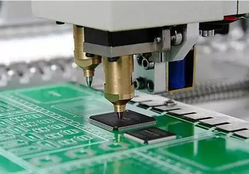
Millimetre-wave radar typically employs single-chip solutions from suppliers such as TI, Infineon, or NXP. These solutions integrate the RF front-end, signal processing, and control unit, featuring multiple transmit and receive channels. Regarding PCB board design for radar modules, several distinct implementation approaches exist:
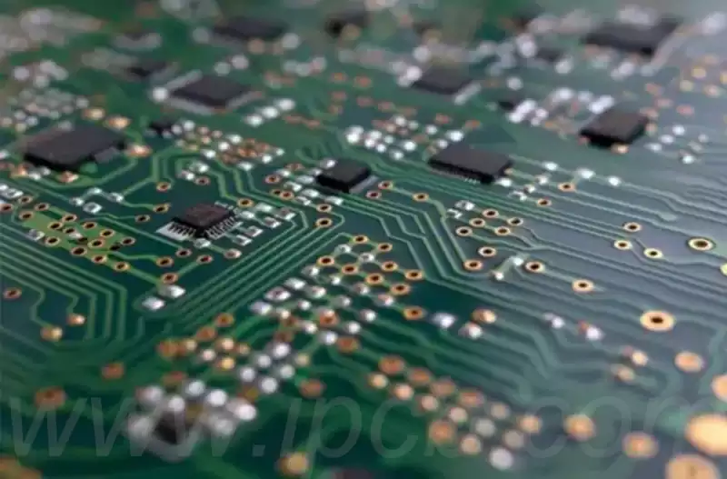
One common approach employs ultra-low-loss PCB materials as the substrate for antenna design, utilising microstrip patch antennas where feedline width precision must be strictly controlled. The remainder of the laminate typically uses FR-4 material. This design offers low cost and ease of fabrication, though attention must be paid to the potential impact of copper foil roughness on loss and consistency.
An alternative approach employs a Substrate-Integrated Waveguide (SIW) circuit for antenna design, utilising FR-4 material for radar control and power planes. Here, the ultra-low loss PCB material is reserved solely for the SIW antenna design, aiming to reduce loss and enhance antenna radiation. To ensure manufacturing precision, thicker PCB material is typically selected to mitigate the impact of copper foil roughness while avoiding process challenges associated with narrow line widths. However, it should be noted that the via processing and positioning accuracy of SIWs are critical.
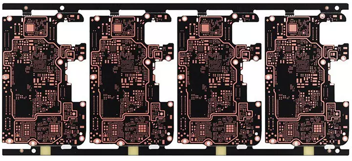
A more advanced design approach involves utilising ultra-low-loss materials for the multilayer board stack-up, selecting this material for partial or complete layers as required. This method enhances circuit design flexibility and integration while further reducing the radar module’s dimensions. However, it entails relatively higher costs and more complex manufacturing processes.
The material properties of PCB boards for 4D millimeter-wave radar require consideration of the following aspects: Electrical characteristics: Stable dielectric constant and low loss enable accurate phase acquisition by the transmit/receive antennas, thereby enhancing antenna gain. The material properties of PCBs for 4D millimeter-wave radar require consideration of the following aspects:
Electrical characteristics: Stable dielectric constant and loss enable accurate phase acquisition by transmit/receive antennas, thereby enhancing antenna gain and scanning angle or range, and improving radar detection and positioning accuracy. Stability of the PCB’s dielectric constant and loss must ensure consistency not only across different batches of material but also minimal variation within a single board, demanding exceptional material stability.
Surface roughness of copper foil: The impact of surface roughness on circuit performance increases with thinner materials. Coarser copper foil types exhibit greater inherent roughness variation, leading to significant fluctuations in dielectric constant and loss. This adversely affects phase characteristics in millimetre-wave applications.
Material reliability encompasses not only high dependability during PCB processing—such as lamination, drilling, and copper foil adhesion—but also long-term and environmental stability. It requires that the electrical properties of PCB materials remain consistent over time and under varying temperature and humidity conditions. The critical importance of this for automotive safety components is self-evident.
In the design and manufacture of 4D millimeter-wave radar, the performance of printed circuit board (PCB) materials is a critical factor.
Electrical Properties The electrical characteristics of materials are the foremost consideration in designing radar sensors and selecting PCB materials. A stable dielectric constant (Dk) and low loss are pivotal to millimetre-wave radar performance. These properties directly influence the phase accuracy of transmit/receive antennas, thereby enhancing antenna gain and improving scanning angles or ranges. The stability of a PCB material’s dielectric constant and loss requires not only consistency between different batches of material but also minimal variation within a single board to enhance the radar’s detection and positioning accuracy. Particularly at millimetre-wave frequencies, thinner circuit boards exhibit a more pronounced glass weave effect, where localised dielectric constant inhomogeneities can cause significant variations in RF circuit and antenna performance.
Copper Foil Surface Roughness The surface roughness of copper foil significantly impacts millimetre-wave circuit performance. For thinner materials, this influence is particularly pronounced. A rough copper surface increases conductor losses, degrading signal integrity and potentially slowing electromagnetic wave propagation. This creates a slow-wave effect, causing the circuit to exhibit a dielectric constant higher than its nominal value. Variations in copper foil roughness also induce substantial fluctuations in dielectric constant and loss, thereby affecting millimetre-wave phase characteristics. In high-frequency applications, smoother copper foil is essential to guarantee electrical conductivity.
Material Reliability Material reliability is crucial for ensuring the long-term stable operation of radar systems. This encompasses not only the reliability of processes such as lamination, drilling, and copper foil adhesion during PCB manufacturing, but also the material’s long-term stability and environmental adaptability. For automotive safety components, the electrical properties of PCB materials must remain stable over extended periods and maintain performance under varying temperature and humidity conditions. 4D millimeter-wave radar delivers highly reliable detection in adverse conditions such as heavy rain, snowfall, darkness, and air pollution.
As an upgraded iteration of conventional millimeter-wave radar, 4D technology significantly enhances perception dimensions, detection range, and resolution, thereby assuming an increasingly vital role in applications like autonomous driving. The electrical characteristics of PCB materials, copper foil surface roughness, and material reliability are core elements in ensuring the high performance and long-term stable operation of 4D millimetre-wave radar. With ongoing technological advancements, continuous optimisation of PCB materials and design solutions will further drive the widespread adoption and performance enhancement of 4D millimeter-wave radar.