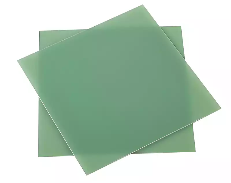
Microwave RF PCB refers to microwave components manufactured using conventional rigid PCB fabrication methods on specific microwave-grade copper-clad laminates.
In printed circuit board wiring for high-speed signal transmission lines, products can currently be categorised into two main types: one category comprises electronic products for high-frequency signal transmission. These products relate to radio electromagnetic waves and transmit signals via sine waves, such as radar, broadcasting, television, and communications (mobile telephones, microwave communications, fibre-optic communications, etc.). The second category comprises electronic products for high-speed logic signal transmission. These devices transmit digital signals and are similarly associated with square-wave electromagnetic wave transmission. Initially primarily applied in computers and similar systems, they have now rapidly expanded into household appliances and communication electronics.
Operating Principles of Microwave RF PCB
Microwave and radio frequency circuits fundamentally constitute systems for propagating electromagnetic waves through conductors and dielectric materials. Their operational principles centre on optimising signal transmission pathways and achieving efficient energy conversion.
- Transmission Modes for High-Frequency Signals
Microwave Transmission Line Theories:
Microstrip: Top-layer signal trace + bottom-layer ground plane. Suitable for designs below 10GHz. Low cost but higher radiation loss.
Stripline: Signal line embedded between two ground planes, offering excellent shielding but requiring complex fabrication.
Coplanar Waveguide (CPW): Signal line and ground plane share the same plane, suitable for millimetre-wave band (>30GHz) integrated designs.
- Synergy between Active and Passive Components
Passive Components:
Filter: Utilises LC resonance principles to filter out out-of-band noise; layout must avoid distributed capacitive coupling.
Power Divider: Achieves equal-amplitude signal distribution via impedance transformation networks, requiring phase consistency error <1°.
Active Components:
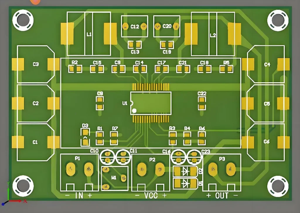
RF chips (e.g., MMIC): Directly soldered to the PCB, relying on high-precision pads and impedance-matching circuits to minimise return loss.
Measured Data: In a Ku-band (1218 GHz) receiver module, filter insertion loss must be <0.5 dB, with a VSWR <1.5:1.
- Grounding and Electromagnetic Field Control
Ground plane integrity: A large, continuous ground plane provides a low-impedance return path. Ferrite beads are employed to isolate analogue/digital grounds when partitioned.
Electromagnetic field boundary constraints: Electromagnetic field propagation is restricted via shielding cans or via shielding arrays.
Failure Case: A satellite communication board experienced a 3dB reduction in antenna gain due to a fractured ground plane. Functionality was restored following temporary repair using a jump wire.
Microwave RF PCB exhibit the following characteristics:
- High Frequency: Operating typically above 1GHz, enabling high-speed data transmission and precise signal processing.
- High precision: Microwave RF circuit boards exhibit exceptional accuracy, delivering high stability and low noise, making them suitable for applications requiring high-precision signal processing.
- High reliability: Microwave RF circuit boards offer outstanding reliability and stability, ideal for applications demanding prolonged, stable operation.
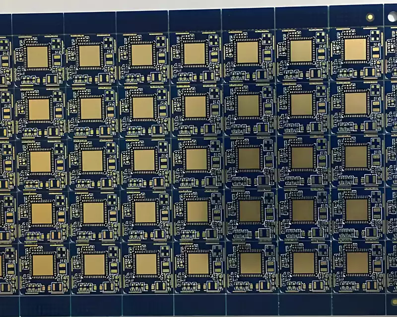
- High integration: Microwave RF circuit boards enable high integration, allowing multiple functional modules to be consolidated onto a compact board, facilitating device manufacturing and maintenance.
- High cost-effectiveness: Microwave RF circuit boards feature low manufacturing costs and excellent value for money, making them suitable for mass production and widespread application.

Considerations for substrate selection in microwave RF PCB:
(1) Permittivity: The permittivity parameter in substrate specifications represents the relative value compared to vacuum. When subjected to an external electric field, a dielectric material generates induced charge that attenuates the field. The ratio of the original external electric field (in vacuum) to the final field within the dielectric material constitutes the relative permittivity (relative permittivity or dielectric constant), denoted as ε_r or D_k, which is frequency-dependent. The dielectric constant is the product of the relative permittivity and the absolute permittivity of free space. When a material with high permittivity is placed in an electric field, the field strength within the dielectric experiences a significant reduction. The relative permittivity of an ideal conductor is infinite.
(2) Loss Factor
Loss Factor: A dimensionless quantity describing the dissipation of electric field energy within a material. It indicates the resistance encountered by an electric field propagating through a material. The loss factor is typically expressed as tan(δ), where δ is the phase angle. The dielectric constant is a complex quantity: its real part represents capacitance, while its imaginary part represents loss. The imaginary part correlates with conductivity; a larger imaginary part indicates greater conductivity and poorer insulating properties. The dielectric constant ε_r (Dk) denotes the real part of the complex dielectric constant, while the loss factor (Df) represents the ratio of the imaginary to real part of the dielectric constant. This ratio provides a relative measure of a material’s ability to conduct electric field energy versus the energy dissipated during this process.
(3) Temperature Coefficient of Dielectric Constant
The temperature coefficient of dielectric constant indicates how ε_r varies with temperature, measured in ppm/°C (parts per million per degree Celsius). For example, RO4350 exhibits a coefficient of +50 ppm/°C, meaning its dielectric constant changes by one per cent within the temperature range of -50°C to +150°C.
Microwave rf pcb, as the core carriers of modern communication technology, directly determine the efficiency and reliability of high-frequency signal transmission. From the optimised design of transmission line structures to the precise coordination of active/passive components, from electromagnetic control of grounding systems to the rigorous selection of substrate parameters, each technological breakthrough propels innovation in fields such as 5G, satellite communications, and radar detection. With the accelerated evolution of 6G and terahertz technologies, future microwave RF circuit boards will continue to evolve towards higher frequency bands, lower losses, and greater integration, providing robust physical foundations for the intelligent world of ubiquitous connectivity.