Rogers PCB assembly is a core process in the manufacturing of modern high-performance electronic devices. This article aims to detail how, during Rogers PCB assembly, exceptional performance and reliability are achieved through meticulous signal protection, optimized microstrip line and grounding techniques, rational component layout and shielding, as well as rigorous post assembly testing and debugging.
Signal Protection in Rogers PCB Assembly
Microstrip Lines and Grounding Techniques
When soldering connectors, ensure microstrip line impedance continuity to avoid reflection losses caused by right-angle traces or abrupt widening.
Ground vias must be densely arranged (λ/10 spacing) to minimize high-frequency ground loop impedance.
Component Layout and Shielding
High-gain RF components (e.g., amplifiers) should be isolated from digital circuits; add metal shielding cavities when necessary.
Adopt the “shortest path” principle for layout to minimize transmission line length effects on phase consistency.
Post-Assembly Inspection and Debugging for Rogers PCB
Non-Destructive Testing (NDT) Applications
Use X-ray inspection to check solder joint porosity (requirement <5%), especially for BGA and QFN packaged components.
Employ infrared thermal imaging to detect dielectric constant (Dk) drift caused by localized overheating.
High-Frequency Performance Validation
Test insertion loss and return loss using a vector network analyzer (VNA), focusing on S-parameters at solder joints.
During rogers pcb assembly, utilizing Rogers PCB materials offers the following advantages:
- Low Loss: Rogers PCB materials exhibit low dielectric loss characteristics, minimizing energy dissipation during signal transmission. This is crucial for high-frequency applications, enhancing signal reliability and transmission distance.
- Thermal Stability: Rogers PCB materials resist deformation and degradation in high-temperature environments. This makes them ideal for high-temperature applications such as aerospace and automotive electronics.
- Dimensional Stability: Rogers PCB materials exhibit excellent dimensional stability, maintaining their shape and size under varying temperature and humidity conditions. This is vital for applications demanding high precision and reliability.
- Multilayer Stacking: Rogers PCB materials support multilayer stacking. By combining different layers of material and circuit boards, higher integration and performance can be achieved.
Precautions for Rogers PCB Assembly:
Material Selection and Storage
Material Selection: The composition and structure of Rogers materials directly impact their performance and quality. Different Rogers material grades (e.g., RO4003C, RO4350B) exhibit distinct dielectric constants and loss characteristics. Therefore, selecting the appropriate material based on specific application requirements is essential to ensure high-performance and reliable circuit boards. For instance, RO4003C is commonly used in high-frequency applications. It is compatible with lead-free soldering processes and possesses processing characteristics similar to FR-4 laminates, helping to reduce manufacturing costs.
Humidity Sensitivity: High-frequency microwave RF circuit boards are sensitive to humidity. Before opening the packaging, boards must be conditioned for 24 hours at 25°C and below 40% humidity to prevent moisture absorption causing solder voids or lamination issues. Rogers 4003C sheets should be stored in a dry environment to avoid performance degradation due to moisture absorption. EM-890K material also exhibits excellent moisture resistance.
Soldering and Assembly Process
Soldering Process: The unique properties of Rogers PCBs demand higher precision in soldering techniques. Compared to standard PCBs, soldering speeds for Rogers PCBs should be appropriately reduced. Both RO4830™ Plus laminates and RO4835 high-frequency boards are compatible with lead-free soldering processes.
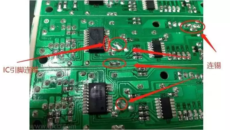
Joint Integrity: Professional soldering equipment and tools must be used during assembly to ensure robust solder joints free from cold solder joints.
Surface Treatment: PCB surface treatment is required prior to soldering. OSP (Organic Solderability Preservative) is a RoHS-compliant copper surface treatment process.
Reflow Temperature Profile: Establishing the reflow temperature profile for soldering Rogers boards to enclosures involves designing pressure blocks, positioning thermocouples, applying pressure, developing the reflow curve, and validation.
Thermal Expansion Coefficient Matching: The thermal expansion coefficients (CTE) of the Rogers substrate and copper foil must match to prevent PCB warping under heat. For example, the X/Y-axis CTE of 4350B is 14 ppm/°C, requiring copper foil with a similar CTE (e.g., electrolytic copper foil with a CTE of approximately 17 ppm/°C).
The rogers pcb assembly process must strictly adhere to a series of technical requirements and operational specifications. From material selection and storage, through precision soldering and assembly techniques, to rigorous testing and debugging, each step is critical to the final product’s signal integrity, high-frequency performance, and long-term reliability.