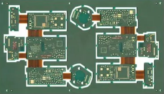
The surface mount technology (SMT) process for flexible printed circuit board (FPC) differs significantly from conventional rigid PCB SMT solutions. The key to successful FPC SMT lies in precise positioning. Due to the flexible nature and insufficient rigidity of FPC substrates, specialised carrier boards are essential for securing and handling the boards during fundamental SMT operations such as printing, component placement, and reflow soldering. The following details key process elements in FPC SMT production: pre-treatment, fixation, printing, component placement, reflow soldering, testing, inspection, and depanelling.
RTR Continuous Roll-to-Roll Production
RTR, short for roll-to-roll or reel-to-reel, denotes continuous roll-based processing. As early as the 1980s, a handful of major global FPC manufacturers established RTR production lines. However, due to immature technology at the time, flexible printed circuit board product yield rates from RTR lines were generally low. It was not until the late 1990s, with the expansion of the TAB and COF markets and the initial maturation of RTR technology, that this continuous production method began to demonstrate superior equipment and process capabilities in TAB and COF flexible printed circuit board manufacturing. By the early 21st century, RTR technology for FPC production had reached a relatively mature stage.
Advantages of RTR
Simplified Operation: The RTR process eliminates the need for operators to mount flexible printed circuit boards onto fixtures, thereby streamlining related workflows.
Damage Prevention: This method effectively avoids creasing and scratching of FPCs during production.
Contamination Reduction: For subsequent processes demanding high cleanliness standards, such as FOG and NCP, RTR mitigates contamination risks from manual handling and environmental factors.
High-End Capabilities: RTR technology meets the requirements for ultra-thin, high-end FPC processes like COF.
Disadvantages of RTR
High Equipment Specialisation: RTR production lines feature highly specialised equipment, limiting their applicability to a relatively narrow range of products.
Significant Initial Investment: The capital expenditure for RTR production equipment is substantial.
Applicability Constraints: This technology is suited to ultra-high-volume flexible printed circuit board production but is unsuitable for multi-variety, small-batch production models.
Fixture-Mounted Production
The core of fixture-mounted production lies in the attachment and fixation of FPCs. With fixture assistance, FPCs are ‘converted’ into ‘PCBs’, enabling SMT processing akin to rigid PCBs. Compared to RTR, fixture mounting offers lower costs and simpler operation, making it the industry’s most prevalent method.
Process Considerations for Fixture Attachment Methods
Substrate Selection and Machining
To ensure FPC flatness during printing and placement, high-precision flexible printed circuit board positioning templates and specialised substrates must be manufactured based on the FPC’s hole positioning data. The diameter of positioning pins on the substrate should correspond to the aperture of positioning holes on both the substrate and the FPC. Many FPCs exhibit non-uniform thickness due to circuit protection or design considerations, featuring thicker and thinner sections, and may even incorporate reinforced metal plates. Consequently, the interface between the carrier plate and flexible printed circuit board requires machining, grinding, and slot cutting tailored to actual conditions. The carrier plate material must be lightweight, high-strength, low-heat-absorption, and rapid-heat-dissipation, while exhibiting minimal warping or deformation after repeated thermal cycling. Common substrate materials include synthetic stone, aluminium plate, silicone rubber sheet, and specialised high-temperature magnetic steel plate.
Standard Substrates: Standard substrates offer straightforward design and rapid prototyping. Common materials are engineering plastics (synthetic stone) and aluminium sheets. Engineering plastic substrates have a lifespan of 3,000 to 7,000 cycles, are easy to handle, provide good stability, absorb little heat, and remain cool to the touch. However, their cost exceeds that of aluminium sheets by more than fivefold.
Aluminium carrier plates: Aluminium plates absorb and dissipate heat rapidly, maintaining uniform temperature throughout. They are easily restored after deformation. Cost-effective with extended lifespan, their primary drawback is high surface temperature, necessitating heat-resistant gloves during handling.
Silicone pads: Silicone pads possess self-adhesive properties, allowing flexible printed circuit board to adhere directly without tape. Removal is straightforward with no adhesive residue. They also exhibit high-temperature resistance. However, silicone degrades chemically during use, diminishing its adhesive strength. Failure to clean promptly further reduces tack, resulting in a shorter lifespan—typically 1,000 to 2,000 cycles maximum—and a higher price point.
Magnetic Fixtures: Magnetic fixtures utilise specially treated high-temperature resistant (350°C) steel plates with enhanced magnetisation, ensuring ‘permanent magnet’ properties during reflow soldering. They offer excellent elasticity, superior flatness, and resist deformation at elevated temperatures. These magnetised steel plates firmly press and flatten the FPC surface, preventing it from being lifted by hot air during reflow soldering and causing soldering defects. This ensures stable soldering quality and improves yield rates. Magnetic fixtures can be used indefinitely unless damaged by human error or accidents, offering a long service life. Additionally, they provide thermal insulation protection for the flexible printed circuit board and cause no damage during board removal. However, magnetic fixtures involve complex design and carry a higher unit cost, offering cost advantages only during high-volume production.
Pre-baking
FPC materials are susceptible to moisture absorption. Moisture-affected FPCs are prone to bubbling and delamination after high-temperature soldering, ultimately leading to scrap. Consequently,flexible printed circuit board suppliers are typically required to use vacuum packaging for incoming materials. Even with vacuum packaging, this is not foolproof. Hence, it is advisable to subject FPCs to pre-baking prior to component placement. Pre-baking conditions must be determined by considering factors such as FPC material, thickness, oven specifications, and baking trays. Suitable temperature, baking duration, and stacking quantities should be established through engineering trials. Post-baking FPCs must cool to room temperature before production, as hot FPCs may cause solder paste thermal collapse. Additionally, cooling duration and extended re-baking time must be monitored, both determined through engineering trials.
Solder Paste Printing for FPCs
FPCs impose no specific requirements on solder paste composition. The size of solder balls and metal content are typically determined by whether fine-pitch ICs are present on the FPC. However, FPCs demand superior printing performance from solder paste. The paste must exhibit excellent thixotropy, enabling effortless printing, release from the stencil, and secure adhesion to the flexible printed circuit board surface. This prevents issues such as stencil aperture blockage due to poor release or solder paste collapse post-printing.
Due to the use of high-temperature-resistant positioning tape on the carrier board, the surface of the mounted FPC may not be perfectly flat. Consequently, the printing surface cannot match the uniform thickness and rigidity of a PCB. Therefore, metal squeegees are unsuitable; instead, polyurethane squeegees with a hardness of 80-90 degrees should be employed. It is advisable for the solder paste printer to be equipped with an optical positioning system, as its absence may significantly impact print quality. Although the flexible printed circuit board is secured to the carrier board, a minute gap may still exist between them. This fundamental difference from rigid PCBs means that equipment parameter settings significantly influence printing outcomes. The printing station is also a critical point for preventing FPC contamination. Operators must wear finger cots during operations, maintain station cleanliness, and frequently wipe the stencil to prevent solder paste from contaminating the FPC’s gold fingers and gold-plated buttons.
FPC Placement
Once the flexible printed circuit board is affixed and secured to the fixture, it behaves much like a PCB, with any unevenness issues resolved. Consequently, the placement process becomes relatively straightforward, differing little from standard PCB placement. However, as FPCs typically carry fewer components, panelised placement is required. The primary challenge in FPC placement thus lies in optimising the efficient utilisation of placement machines.
When FPCs arrive as panelised assemblies:
The placement process for panelised flexible printed circuit board is relatively straightforward, with the primary focus being the impact of defect rates per panel on placement efficiency. Even under the highest defect rate scenarios, the placement machine must maintain the highest possible CYCLE TIME.
When FPCs arrive as single boards:
Single-board FPCs require panelisation onto fixtures prior to production. The number of panels directly impacts placement efficiency. As FPCs predominantly feature chip components with limited ICs and connectors, it is advisable to set the panel count as a multiple of the number of segment holders per arm on the placement machine. For instance, on a Siemens D4 placement machine with 12 segment holders per arm, FPC panels should be configured as 12 panels or multiples thereof. The advantage of this panelisation method is that each cycle can be fully loaded with components, avoiding waste and facilitating programme optimisation.
When a single FPC board is panelised into 12 panels, positional deviations may occur for each FPC due to limitations in fixture positioning accuracy and FPC positioning hole precision. Consequently, mark point recognition is required for each flexible printed circuit board during placement. For instance, a 12-panel assembly necessitates identifying 24 mark points, significantly reducing efficiency. Solder paste mark point technology can be employed, reducing mark points to just two while markedly improving quality issues such as component standing and cold solder joints. Prior to implementing solder paste MARK point technology, it is essential to verify whether the placement machine’s camera incorporates blue light and a 45-degree light source. If not, the camera must be modified to include a 45-degree blue light source.
Reflow Soldering of Flexible Printed Circuits (FPC)
During the reflow soldering process, a forced-air convection infrared reflow oven must be employed to ensure uniform temperature distribution across the FPC, thereby minimising soldering defects. If flexible printed circuit boards are secured using single-sided adhesive tape, deformation may occur in the central area during convection due to the tape only fixing the four edges. This can cause pad tilting, allowing molten solder (liquid solder at high temperatures) to flow, resulting in solder voids, bridging, and solder balls, leading to elevated process defect rates.
Temperature Profile Testing Method: Due to the heat absorption properties of the carrier board and the variety of components on the FPC, their rate of temperature rise and heat absorption during reflow vary. Therefore, meticulous configuration of the reflow oven’s temperature profile significantly impacts soldering quality. A prudent approach involves placing two carrier boards with flexible printed circuit board before and after the test board, spaced as in actual production, with components mounted on the FPC of the test board. Solder high-temperature solder wire to attach the test probe to the test point, securing the probe lead to the carrier board with high-temperature resistant tape. Crucially, the tape must not cover the test point. Test points should be selected near solder joints along the carrier board edges and QFP pins, ensuring test results accurately reflect real-world conditions.
Temperature profile configuration: During oven calibration, due to FPC’s poor thermal uniformity, a temperature profile comprising heating/holding/reflow stages is recommended. This approach facilitates easier control of parameters across temperature zones while minimising thermal shock effects on FPC and components. Based on experience, it is advisable to set the oven temperature to the lower limit of the solder paste specification requirements. The reflow oven airflow should typically be set to the lowest velocity achievable by the oven. The reflow oven conveyor chain must operate stably without vibration.
FPC Inspection, Testing, and Depaneling
As the carrier board absorbs heat during the reflow process, particularly aluminium carrier boards, it emerges from the oven at a high temperature. Therefore, it is advisable to install forced-air cooling fans at the exit to facilitate rapid cooling. Concurrently, operators must wear heat-resistant gloves to prevent burns from high-temperature carriers. When removing fully soldered FPCs from the carrier, apply even pressure without excessive force to avoid tearing or creasing the flexible printed circuit board.
Removed FPCs require visual inspection under a magnifier with at least 5x magnification, focusing on surface defects such as residual adhesive, discolouration, solder contamination on gold fingers, solder balls, IC pin solder voids, and bridging. Due to potential surface irregularities, AOI (Automated Optical Inspection) yields a high false-positive rate, rendering it generally unsuitable for flexible printed circuit board inspection. However, with specialised test fixtures, FPCs can undergo ICT (In-Circuit Testing) and FCT (Functional Component Testing).
As FPCs are often supplied as multi-panel assemblies, depanelisation may be required prior to ICT and FCT testing. While blades or scissors can be used for depanelisation, this approach yields low efficiency, poor quality, and high scrap rates. For high-volume production of irregularly shaped FPCs, it is advisable to manufacture specialised flexible printed circuit board punching separation moulds for die-cutting. This method significantly enhances operational efficiency while producing FPCs with neat, aesthetically pleasing edges. Furthermore, the low internal stresses generated during punching effectively prevent solder joint cracking. Panelised FPCs require separation, with the method chosen depending on the panel’s connection configuration.
During SMD placement on FPCs, precise positioning and secure fixation are paramount, as their quality directly impacts assembly outcomes. Subsequent critical steps include flexible printed circuit board pre-baking, solder paste printing, component placement, and reflow soldering. The SMT process for FPCs presents significantly greater challenges than that for rigid PCBs, making precise parameter setting paramount. Rigorous production process management is equally vital, requiring operators to strictly adhere to every stipulation in the Standard Operating Procedures (SOP). Line engineers and In-Process Quality Control (IPQC) personnel must intensify patrol inspections to promptly identify production line anomalies, analyse root causes, and implement necessary corrective actions. Only through such measures can the defect rate on FPC SMT production lines be maintained within the tens of parts per million (PPM).