Arduino PCB boards typically refer to printed circuit boards specifically designed for Android devices such as smartphones, tablets, and television boxes. Similar to PCBs in other devices, arduino pcb boards form one of the core hardware components of these devices. They house all critical electronic components—such as processors, memory, and wireless communication modules—and interconnect them via circuitry.
An Arduino PCB Board provides the physical foundation for an electronic assembly, where all electronic components—such as microcontrollers, sensors, and connection ports—interconnect via conductive traces on the board. In standard Arduino development boards (e.g., Arduino Uno), the most critical components include:
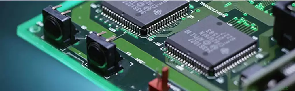
Microcontroller (MCU): Typically the Atmega328P (used in the Arduino Uno), serving as the brain of the Arduino, responsible for processing input signals and controlling outputs.
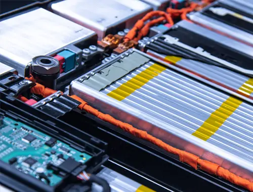
Power Management Circuitry: Including the USB interface and voltage conversion modules, used to supply power to the Arduino board.
Digital and analogue I/O pins: These pins facilitate data communication with external devices.
Crystal oscillator: Supplies the microcontroller with a clock signal, ensuring the board operates at its intended frequency.
Functions of the Arduino PCB boards:
Electrical Connections and Signal Transmission
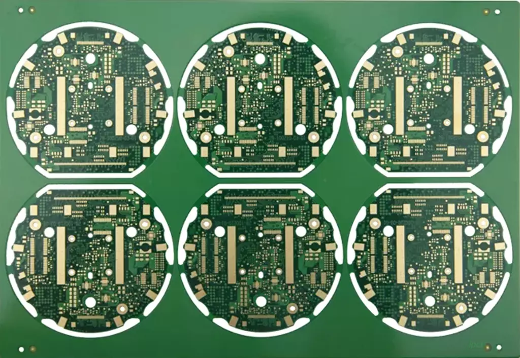
Through meticulously designed conductor layouts, the Arduino PCB boards interconnects electronic components such as the processor, memory, display, camera, and sensors into a complete circuit system. For instance, within smartphones, the PCB ensures rapid transmission of high-speed data signals between the processor and memory, guaranteeing system fluidity. Simultaneously, it stably distributes power signals to maintain normal operation of all components.
In high-speed digital circuits, PCB design must account for signal integrity and impedance matching. Differential signal transmission techniques are employed to minimise loss and electromagnetic interference, thereby enhancing signal transmission efficiency.
Mechanical Support and Structural Integration
PCBs provide robust mechanical support for electronic components, securing minute precision parts to maintain stable spatial relationships during production, transportation, and use. For instance, in laptops, PCBs must support heavier components like processors and graphics cards while ensuring stable connections during opening, closing, and movement.
Android devices frequently employ modular designs, integrating specific functions (such as charging ports, side buttons, and SIM card slots) onto independent sub-boards connected to the mainboard via PCBs. This optimises spatial layout and reduces maintenance costs.
Thermal Management
Heat generated by electronic components must be dissipated through the PCB. Arduino PCB boards utilise thermal conductive materials like copper foil to transfer heat to heat sinks or heat spreaders, which then dissipate it via air convection. For instance, high-power devices (such as server CPUs) often incorporate heat sinks directly onto the PCB or employ metal-based PCBs (e.g., aluminium or copper substrates) to enhance thermal performance.
In extreme environments (e.g., aerospace equipment), PCBs must exhibit superior environmental resilience to withstand high temperatures, cryogenic conditions, humidity, and other challenges.
Signal Shielding and Isolation
As circuit integration and signal frequencies increase, electromagnetic interference (EMI) issues intensify. Android PCBs employ shielding layers (e.g., copper foil shielding or metal shielding enclosures) to encapsulate interference-prone areas, preventing external interference ingress and internal signal leakage.
Multi-layer PCB structures minimise crosstalk by strategically arranging power planes, ground planes, and signal layers, leveraging the shielding effect of ground and power planes. Scenarios demanding stringent electromagnetic compatibility (e.g., medical or communication equipment) require adherence to rigorous design specifications.
Modular and Standardised Design
Arduino PCB boards employ standardised design principles, unifying dimensions, interface specifications, and routing rules to enhance production efficiency and simplify maintenance. For instance, during equipment failure, faulty modules (such as power supply or signal processing units) can be swiftly located and replaced without extensive disassembly.
Modular design shortens development cycles while facilitating functional expansion and upgrades. For example, Android development boards support embedded projects like AI visual analysis and edge computing by combining core boards with expansion backplanes.
The Process of Designing an Arduino PCB Board
Defining Requirements and Specifications
Before commencing design, it is crucial to clarify the intended purpose of the Arduino pcb board. Are you aiming to create a base board similar to the Arduino Uno, or do you wish to integrate additional functionalities such as wireless communication or sensor interfaces? Once requirements are established, you can proceed to select suitable components, determine the number of required I/O ports, power supply specifications, and other essential parameters.
Selecting Suitable CAD Tools
Designing a PCB requires the use of PCB design software. Numerous free and paid tools are available, including:
KiCad: Free and powerful, suitable for advanced users.
Fritzing: Extremely beginner-friendly, enabling rapid design and prototyping.
Altium Designer: A professional-grade tool suited to more complex projects.
These tools typically include Arduino-related schematic and PCB library files, which can be directly imported into your design to minimise repetitive work.
Drawing Schematics
Select appropriate components based on your requirements and draw the schematic within the CAD tool. During schematic design, ensure all aspects—power supply, current, voltage—comply with Arduino design specifications, and verify correct connections between components.
PCB Layout Design
Layout constitutes a critical phase of the design process. By strategically arranging components, ensure signal paths are as short and stable as possible to minimise noise interference. Key considerations include:
Ensure power and ground traces are sufficiently wide and securely connected to prevent voltage fluctuations during high current flow.
Keep high-frequency signal paths as compact as feasible and avoid prolonged exposure.
Allow adequate spacing between components to facilitate soldering and thermal dissipation.
Design Rule Checking
Upon completing the PCB design, conduct a Design Rule Check (DRC) to ensure the board complies with the manufacturer’s specifications, preventing issues such as excessively narrow trace widths or insufficient pin lengths.
Generate Gerber Files and Manufacture the PCB
Once the design is finalised, generate Gerber files—the standard format used by PCB manufacturers to produce the circuit board. Submit these files to the PCB manufacturer, who will fabricate the board according to your design.
Assembly and Testing
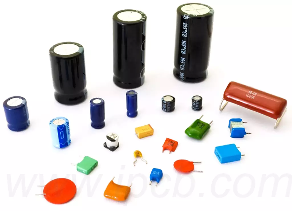
Upon PCB production completion, the next step involves component assembly and testing. This entails soldering all necessary components (such as microcontrollers, resistors, capacitors, etc.) and programming the Arduino firmware onto the microcontroller using a programmer. Testing is a critical step to ensure the circuit functions correctly.
How to Optimise Arduino PCB Board Design
Reducing Noise Interference
Noise interference is a common issue in high-frequency circuits. To mitigate interference, employ appropriate filters, adjust the layout to minimise signal paths, and avoid crossing high-current lines with sensitive signal lines.
Optimising Power Supply Design
For Arduino boards, the power supply circuit is paramount. Ensure the board can be reliably powered externally and that internal power conversion modules meet current demands. Design with sufficient current margin and pay attention to power line routing.
Ensuring Reliable Soldering Quality
Particularly in DIY or small-batch production, guaranteeing soldering quality is critical. Opting for surface-mount devices (SMDs) enhances PCB density and facilitates automated production.
Arduino PCB boards deliver stable signal transmission, power management, and thermal dissipation for smart devices, ensuring high performance. Arduino PCB boards, as the core of open-source hardware, empower developers with greater innovation scope for rapid electronics project realisation. During design, optimise signal integrity, power management, and noise control to guarantee product reliability and efficiency.