One day in the future, self-driving vehicles may be safer than the motor vehicles driven by drivers today. But before drivers start to let go of the steering wheel, some electronic functional components must become standard in commercial vehicles, including millimeter-wave radar systems, cameras and automotive radar antennas. Radar seems to be more easily associated with battlefields than roads. But it is steadily becoming a very reliable sensor technology, providing electronic safety functions for modern commercial vehicles as part of the advanced driver assistance system (ADAS) technology in modern cars.
Millimeter-wave radar sensors and automotive radar antennas are key core components in automotive active safety systems (ADAS). The performance of millimeter-wave radar sensors is affected by many factors, and PCB circuit materials are one of the key factors affecting the performance of sensor circuits. To ensure that millimeter-wave sensors have high stability and performance consistency, many key parameters in PCB circuit materials need to be considered.
Antennas, as important components for millimeter-wave transmission and reception, are one of the key designs for the effective operation of automotive radar antennas, and also affect whether millimeter-wave radars can win the market. If you pass by a radar base station, you must be impressed by its huge mechanical scanning antennas, which are obviously not suitable for cars with demanding appearance and volume requirements. So how should the antenna of millimeter-wave radar be designed? First, the antenna should be produced in large quantities and at low cost. Second, the antenna should be designed to be easy to install on the head of the car. At the same time, the antenna must be integrated into the car without affecting the appearance of the car.
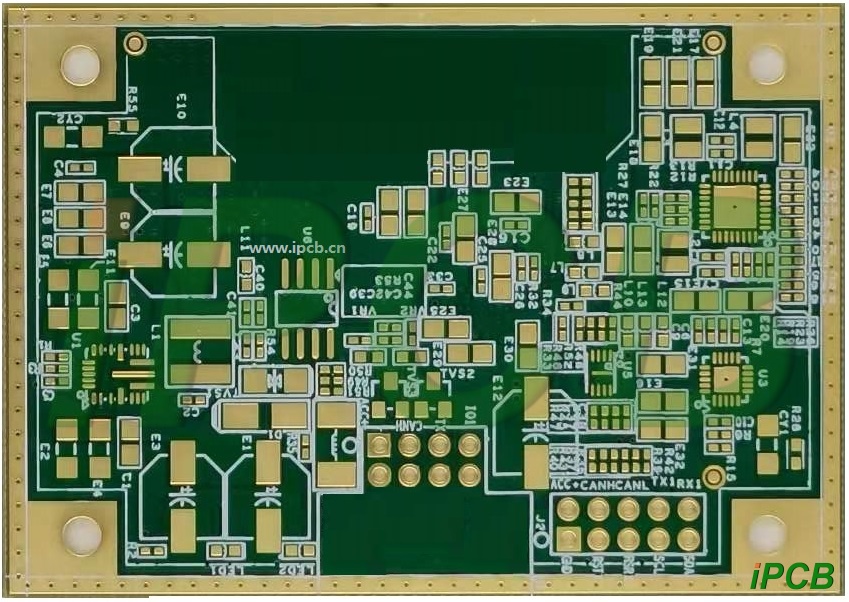
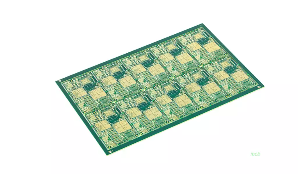
Theory and practice have proved that the antenna has the highest transmission and reception conversion efficiency when the length of the antenna is 1/4 of the wavelength of the radio signal. Therefore, the length of the antenna will be determined by the frequency or wavelength of the transmitted and received signals. Fortunately, the wavelength of the millimeter wave is only a few millimeters, so the antenna of the millimeter-wave radar can be made very small, and multiple antennas can be used to form an array antenna to achieve the purpose of a narrow beam. At present, the mainstream solution for millimeter-wave radar antennas is microstrip arrays. The most common one is designed to be integrated on the PCB board “microstrip patch antenna”, and several open-circuited microstrip lines are laid on the layer on the PCB board to form an antenna.
Compared with general microwave antennas, microstrip antennas have the following advantages: (1) small size, light weight, low profile, and can conform to the carrier (such as aircraft); (2) low cost, suitable for mass production with printed circuit technology; (3) diverse electrical properties. The maximum radiation direction of microstrip elements of different designs can be adjusted from side-fire to end-fire, and various polarizations can be easily obtained; (4) easy to integrate, and can be integrated with active devices and circuits into a unified component. The above advantages greatly meet the requirements of low cost and small size of automotive radar antennas.
Of course, due to the short wavelength of millimeter waves, the circuit is very easy to emit dispersion and generate high-order modes, and the dielectric constant and loss of the substrate material also change significantly with the increase of frequency. In order to ensure stable and consistent circuit performance, millimeter-wave radars need to select high-frequency PCB substrates with stable dielectric constants and low loss characteristics. The expansion of the automotive millimeter-wave radar market also drives the competition of high-frequency substrates and substrate manufacturers in this market. The main domestic and foreign high-frequency PCB substrate manufacturers are: Rogers (USA), Taconic (USA), Isola (Germany), Shengyi Technology (China), Hushi (China), etc.
When multiple radar targets are close to each other, such as two cars in a traffic jam, accurate radar distance resolution is required to distinguish the detected objects. Shorter radar pulses can be used to detect targets, although shorter pulses or any type of signal will have less energy reflected back from the target to the radar receiver. More energy can be added to shorter pulses by using pulse compression, where phase or frequency modulation can increase its power level. For this reason, radars based on frequency modulated continuous wave (FMCW) signals
(also called “linear frequency modulation” signals) are commonly used in vehicle radar systems.
Self-driving cars will use many different electronic technologies to provide guidance, control and safety, including sensors using light and electromagnetic waves. Millimeter-wave frequency radars will widely use signal frequency ranges and circuit technologies that were once considered unique, experimental, or even used only for military purposes. The increase in the use of millimeter-wave radar is a trend that more and more electronic technologies and circuits are integrated into motor vehicles, providing convenience and support for drivers, making vehicles safer to drive, and freeing owners and operators from the “task” of driving vehicles. The use of high-frequency electronic devices in commercial motor vehicles may even trigger a whole new way of interacting between drivers and vehicles. At the very least, the use of technologies such as millimeter-wave radar will change the definition of “driving” a motor vehicle.
The design of these vehicle-mounted millimeter-wave radar systems usually starts with an antenna, and this antenna is usually a high-performance printed circuit board (PCB) antenna, i.e., an automotive radar antenna, which is installed in different locations to detect or “illuminate” targets by transmitting and receiving low-power milliwatt-level millimeter-wave signals. The vehicle’s radar and other electronic systems use different methods to provide information about the vehicle’s surrounding environment for use by the vehicle’s surrounding object detection and classification algorithms. The signal of the vehicle-mounted radar may be in pulsed or modulated CW form.
Vehicle-mounted radar systems have been used for blind spot detection at 24GHz for some time. However, over time and as competition for spectrum from other functions such as wireless communications increases, automotive radar systems are moving to higher frequencies with narrower bandwidths, such as the approximately 1 GHz wide band centered at 77 GHz, and the 79 GHz band.
Whether at 24, 77 or 79 GHz, the performance of PCB antennas is critical for these automotive radar systems, which need to transmit to a target and receive the reflected signal almost instantaneously, such as the target being another vehicle. Key PCB antenna performance parameters include gain, directivity and efficiency, and low-loss circuit materials are essential to achieve good PCB antenna performance. Long-term reliability of automotive radar antennas is also very important, because these compact antennas and their high-frequency transceiver circuits must also continue to operate uninterrupted (while the vehicle is in operation) and operate reliably in a more challenging operating environment – commercial motor vehicles.
In addition to using guidance/warning systems such as radar, lidar and sonar, motor vehicles will also use wireless communications with other vehicles to create electronic awareness of the surrounding environment, such as traffic and obstacles. This wireless communication will include PCB antennas and high-frequency circuits as part of a “vehicle-to-everything” or “V2X” communication system to maintain awareness of other vehicles and traffic around them. The combination of multiple electronic technologies, including communications, lidar, and radar, will help form a safety barrier around each car and provide its central control computer with the input data required for safe autonomous vehicles.
Radar technology has the advantage over other in-vehicle electronic safety technologies that it can operate effectively in a variety of adverse weather conditions, even when acoustic and optical-based ADAS technologies (including cameras) may be severely degraded. Radar systems have the advantage of being able to work 24/7, but radar systems for autonomous vehicles also require stable, high-performance PCB antennas for both transmit and receive functions. Achieving angular and high lateral resolution and repeatable, consistent performance for PCB antennas requires circuit materials with properties that support operation at such high frequencies and environments.
High-performance PCB antenna materials for millimeter-wave frequencies must have low loss characteristics and good dielectric constant (Dk) tolerance variations from batch to batch and under varying vehicle environmental conditions such as temperature and humidity. In addition, the circuit material of the automotive radar antenna should also have a smooth copper foil surface, low loss factor (Df) and low moisture absorption.
Temperature Variation of Dielectric Constant (TCDk)
The dielectric constant of circuit materials changes with temperature. This temperature-dependent parameter helps engineers understand the performance changes that may occur in circuit materials. The change of the dielectric constant of a material with temperature is usually defined as TCDk. The smaller the change, the more stable the material performance (in terms of temperature). The TCDk value of an ideal circuit material will maintain a fixed Dk value even if the temperature changes. Its TCDk value is 0ppm/℃. However, in the real world, the Dk value will change with the temperature of the circuit material. Only circuit materials with very low TCDk values can be considered as materials with stable Dk with temperature. Usually, the absolute value of TCDk is less than 50ppm/℃. When an application requires a circuit to withstand a wide operating temperature range and maintain stable performance at all times – such as the application of automotive radar sensors, which need to maintain precise measurement accuracy at all times and may operate at different operating temperatures – the material’s TCDk parameter is one of the key parameters to consider.
Two materials in the same resin system will not have the same TCDk characteristics. For example, although PTFE is a high-frequency circuit material with excellent performance and low loss, different circuit materials based on PTFE may have very different TCDk characteristics. The Dk of some PTFE-based circuit materials varies greatly with temperature, with TCDk values of 200ppm/℃ or even higher.
At the same time, some PTFE-based circuit board materials can provide TCDk characteristics close to the ideal state.
Autonomous vehicles will become the focus and direction of future development of the automotive industry, and the unique advantages of millimeter-wave radar sensors make them an indispensable component of autonomous vehicles and help make autonomous vehicles possible. PCB circuit materials are the basis of millimeter-wave radar sensors. Selecting materials with stable dielectric constants and low loss characteristics is the starting point for designing millimeter-wave radar sensors.
However, in order to ensure that the radar sensor has stable and consistent circuit performance, the type of copper foil used in the material and the surface roughness of the copper foil, the change of dielectric constant with temperature, the hygroscopicity of the material, and whether the material contains glass cloth to bring about glass fiber effect all need to be considered, so as to ensure that the automotive radar antenna can accurately detect and locate objects and speeds.
