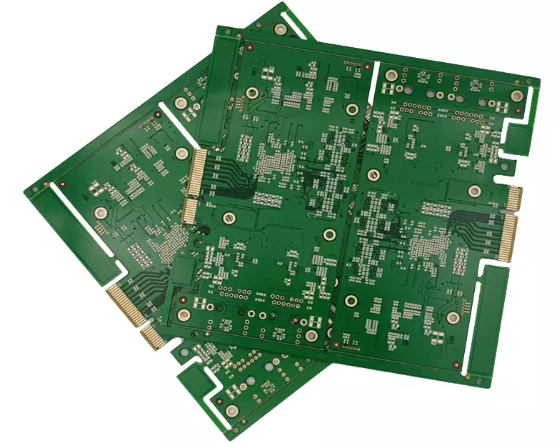
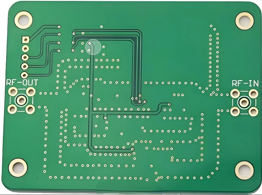
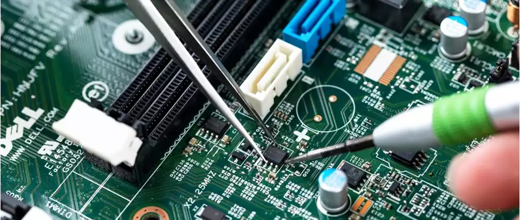
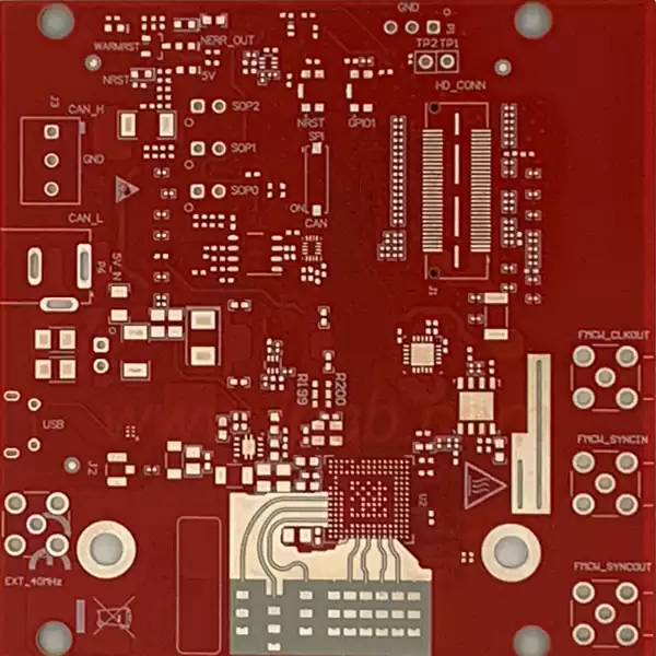
The board edge connector is an important electronic component that plays an indispensable role in modern electronic equipment. Its main function is to provide electrical connection and signal transmission, usually used to connect the motherboard with other peripheral devices or modules.
The board edge connector usually consists of multiple metal contacts, insulating material, and a mechanical support structure. The metal contacts are located at the edge of the connector and are inserted to make connections to other boards or devices. Common materials include metal alloys for the contacts and plastics for the insulation and support. Edge connectors are designed not only for electrical performance, but also for mechanical stability and durability to cope with the wear and vibration of everyday use.
The shape and size of edge connectors are usually designed according to specific application requirements. Standardised edge connector specifications such as PCI, PCIe and DIMM enable compatibility between different manufacturers and products. This standardised design dramatically simplifies the production process and facilitates the rapid assembly and maintenance of electronic equipment.
The basic principle of operation of board edge connectors is to make contact with the corresponding slot through metal contacts in order to achieve an electrical connection. When the connector is inserted into the slot, the board edge connector contacts come into contact with the metal contacts inside the slot to form a continuous electrical path. This process can be divided into the following steps:
Insertion Connection: The metal contacts of the edge connector are inserted into the slot of the motherboard. This process is usually achieved by mechanical force, and the connector is designed to ensure that its contacts fit precisely into the slot’s contact points.
Contact build: Once the connector is fully inserted into the slot, the metal contacts establish an electrical connection with the contacts in the slot. At this point, current can flow freely between the connector and the motherboard.
Signal Transmission: Once the electrical connection is established, signals can be transmitted between devices through these contacts. Data can be passed between the connector interfaces in the form of current or voltage to exchange and communicate information.
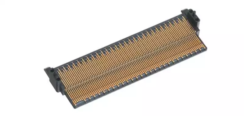
Methods and Strategies for Ensuring Signal Integrity in Board Edge Connector
Design Considerations
Signal integrity is greatly affected by the design phase, and a proper design can effectively reduce signal interference and loss. Below are a few key design considerations that should be taken into account:
Impedance Matching: Ensuring that the impedance of the connector matches the impedance of the board can effectively reduce signal reflection and loss. Avoid signal distortion caused by mismatched impedance, which is usually required to be 50Ω or 75Ω depending on the application requirements.
Signal Alignment: Using shorter, straight path alignments can reduce signal loss and interference during transmission. Avoid excessive bends and crossovers to reduce the effects of parasitic inductance and capacitance.
Ground plane design: A well-designed ground plane provides the necessary return path for the signal. This helps to reduce common mode noise and signal crosstalk, thus improving signal integrity.
Choosing the right material
Material selection is also critical to signal integrity. The following are recommended material properties:
Low-loss materials: Using low-loss PCB substrates (e.g., FR-4 or high-frequency materials) reduces signal attenuation during propagation. It is important to select materials with low dielectric constants and low loss factors for high frequency applications.
Suitable conductor material: Selecting a highly conductive metal (e.g. copper) as the board edge connector contact material reduces contact resistance and improves conductivity. In addition, the surface treatment of the metal improves the signal transmission quality.
Testing and Verification
Once the design is complete, it is critical to test and verify the system to ensure signal integrity.
Time Delay and Jitter Tests: Using an oscilloscope to measure the time delay and jitter of a signal, the quality of the signal can be judged by evaluating the signal’s waveform. These tests can help engineers identify potential signal integrity issues.
S-parameter Analysis: Analyse the signal characteristics of a transmission line using S-parameters (scattering parameters), which provide detailed information on insertion loss, return loss and crosstalk, thus facilitating design optimisation.
Electromagnetic Simulation: Electromagnetic field simulation can be performed to predict the behaviour of a signal under different environmental conditions. This prediction can help designers adjust their designs to meet signal integrity requirements.
Appropriate Connector Selection
Choosing the right connector is critical to maintaining signal integrity:
High-performance connectors: Choose high-performance board edge connectors designed to meet industry standards, such as PCIe, SATA, etc. These connectors are often rigorously tested to ensure good signal transfer performance.
Multi-Contact Designs: Using multi-contact connectors increases the contact area and reduces contact impedance, which improves the stability and reliability of signal transmission.
Board edge connectors play a critical role in modern electronic devices, and their design, material selection, testing and verification, and connector selection all have a profound impact on signal integrity. Through careful design and rigorous testing can ensure that the edge connector in the complex and changing electronic environment to provide stable and reliable electrical connections and signal transmission. With the continuous progress of technology, the future of the edge connector will be more intelligent and efficient, for the performance of electronic equipment to improve and provide strong support for innovation and development. Therefore, in the design and manufacturing process of electronic equipment, great importance should be attached to the selection and application of edge connectors to ensure the stability and reliability of the entire system.
