Lead melting points and selection of lead free solder
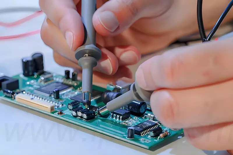
The lead melting points is generally 183°C-190°C, depending on the ratio of lead to tin. Lead solder is a type of solder commonly used to connect electronic components, and its components are mainly lead and tin. In practice, in order to improve the strength and heat resistance of the solder joints, sometimes also add other […]