What is semiconductor packaging?
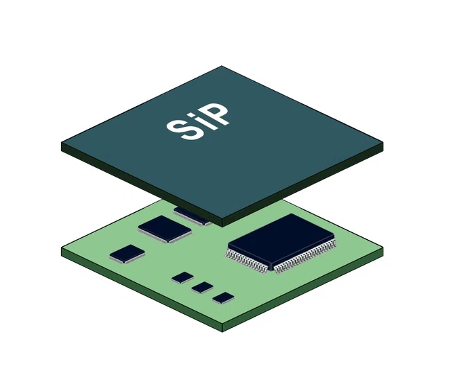
What is semiconductor packaging? Semiconductor Packaging is the process of processing a tested wafer into an individual chip according to the product model and functional requirements. The purpose of traditional packaging is to fix, lead and seal the cut chip, but with the advent of the post-Moore’s Law era, more and more steps that need […]