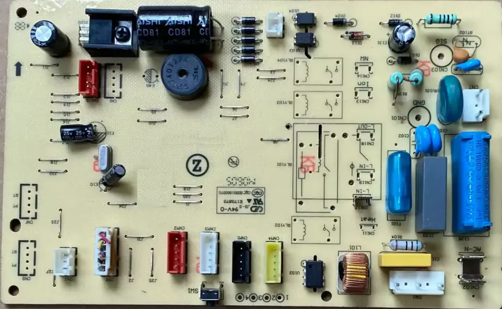
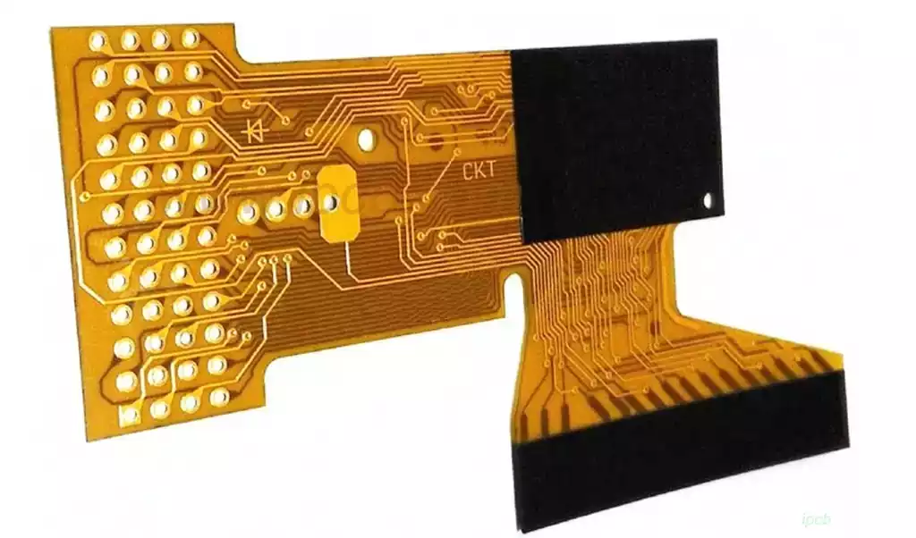
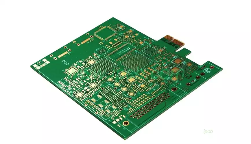
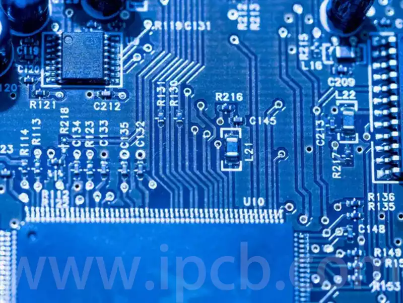
The circuit board on ac unit is a key component that ensures the efficient operation of the system. It acts as the central nervous system, controlling and coordinating the various functions of the AC unit. The core function of the circuit board is to receive and process data from various sensors. These sensors, which usually include temperature and humidity sensors, are responsible for monitoring the state of the indoor environment in real time. For example, the temperature sensor monitors the current indoor temperature and compares it to the set temperature. When the room temperature is higher than the set value, the circuit board signals the compressor to start for cooling.
On the circuit board on ac unit power circuit troubleshooting methods
, a microcontroller is integrated, which is the brain of the board. After receiving the input data from the sensors, the microcontroller calculates the required control instructions through an internal programme and then sends messages to the compressor, fan and other components. The control commands not only include starting or stopping the unit, but may also adjust the operating speed and refrigerant flow rate for optimal air conditioning.
The circuit board also contains relays, fuses and various electronic components to protect and control the flow of current. For example, when the voltage is too high or too low, the circuit board can cut off the power via a relay to prevent damage to the unit. At the same time, the circuit board constantly monitors the working status of the components to ensure that they are functioning properly.
Key Components of circuit board on ac unit
The circuit board on ac unit consists of the main chip, driver chip, amplifier, power supply module and numerous circuit components. Among these components, the main chip plays a central role, responsible for leading and regulating the workflow of the entire circuit board.
Functions and roles of each part
Main chip: dominates the operation of the entire board, including signal output control, signal input reception and processing.
Driver Chip: Ensure the motor rotates according to the instruction and keep its running state stable.
Amplifier: Responsible for enhancing the signal strength and transmitting the enhanced signal to the output port.
Power supply module: provides the necessary power supply for the whole circuit board.
Circuit components: including capacitors, resistors, diodes, etc., which play a key role in the circuit such as current limitation, energy storage, discharge, isolation and voltage conversion.

Circuit board on ac unit power circuit troubleshooting methods
Circuit board on ac unit power circuit troubleshooting methods
power circuit failure phenomenon is usually divided into two categories: one is the fuse remains intact, but the circuit works abnormally; the other is the instant the fuse burns out when you switch on the machine. In the face of the first situation, you can use the AC voltage block of the multimeter to detect whether the primary and secondary of the transformer have 220V and 10-13V respectively. If these voltages are detected, the next step should be switched to the DC voltage block of the multimeter to check whether the 7812 and 7805 voltage regulator components are respectively outputting +9 to +12V and +5V DC voltage, in order to determine the specific location of the fault. As for the second type of fault, that is, the boot that burns the fuse, which usually means that there is a short circuit in the circuit. At this point, you need to use the ohm stop of the multimeter to measure the resistance value of the circuit to locate the location of the short circuit. In addition, you can also use the split method to further troubleshooting, such as disconnecting the primary winding of the transformer and then re-energise the test, if the fuse is still burnt, then there may be a short circuit in the varistor or ceramic capacitor; on the other hand, there may be a short circuit in the transformer or rectifier and other components.
Circuit board on ac unit temperature-sensitive circuit troubleshooting methods
Thermistor has a negative temperature coefficient characteristics, that is, as the temperature rises, its resistance value will decrease; Conversely, the temperature decreases, the resistance value will increase. In the standard room temperature of 25 degrees, the resistance value of the thermistor is usually in the range of 5-20KΩ (the specific value varies depending on the equipment model). In order to detect whether the thermistor is damaged or not, you can use the ohm stop of a multimeter to measure its resistance value. If the measurement shows an infinite or abnormally small resistance value, this indicates that the thermistor may have failed.
The core responsibility of the circuit board on ac unit is to process the data provided by the sensors and direct the operation of the components based on this data. It relies on the microcontroller to receive the information sent by the temperature and humidity sensors to continuously monitor the indoor environmental conditions. Once the room temperature is found to be out of the preset comfort range, the board reacts quickly by issuing commands to activate the compressor and adjusting the fan speed to achieve a cooling effect. In addition, the board has the ability to automatically regulate the refrigerant flow to optimise the cooling performance of the air conditioner and enhance user comfort.


