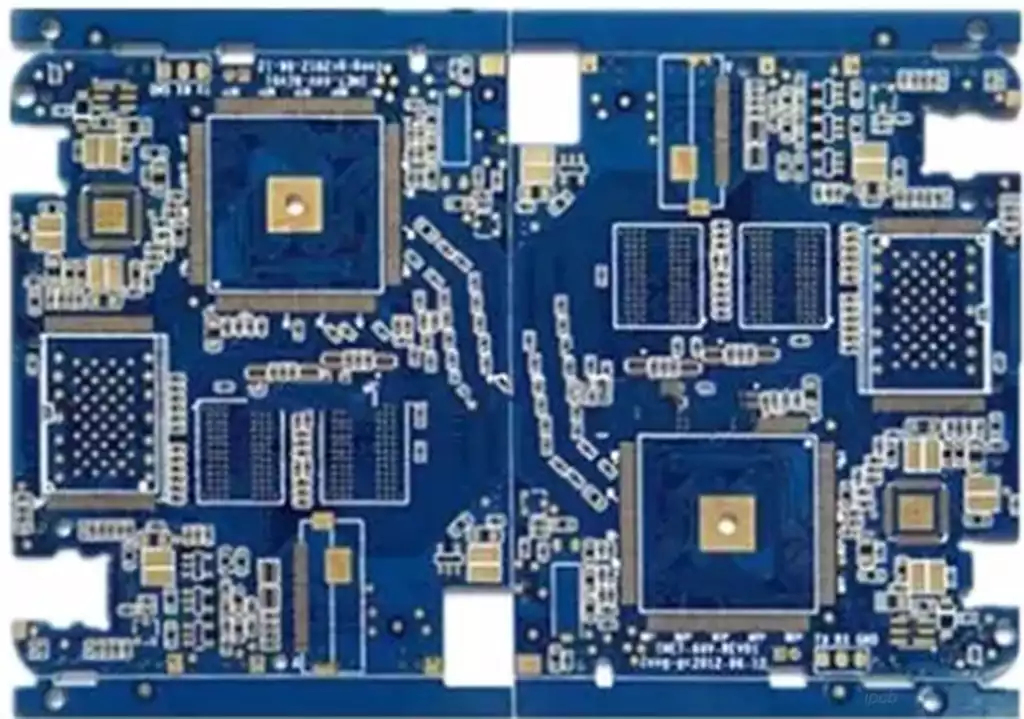
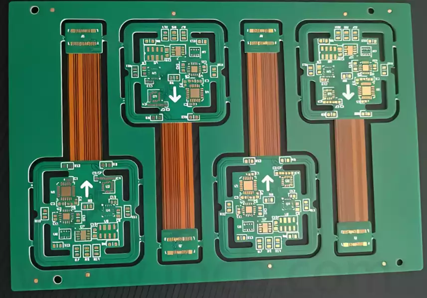
The trend in PCB design is moving towards lighter, thinner, and smaller boards. In addition to high-density circuit board design, there is also the important and complex field of three-dimensional connection assembly for rigid-flex circuit boards. Rigid-flex boards are also known as rigid-flexible boards. With the emergence and development of FPC circuit boards, rigid-flex circuit boards (rigid-flex boards) have gradually been widely adopted in various applications.
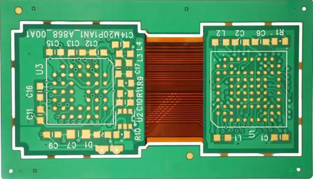
Therefore, rigid-flex cirucit boards are created by combining flexible circuit boards with traditional rigid circuit boards through various processes, according to relevant process requirements, to form a circuit board that simultaneously possesses the characteristics of both FPC circuit boards and PCB boards.
Key points in rigid-flex circuit boards design:
1) Design requirements for flexible zones:
1.1) Avoid sudden expansions or contractions in the circuit design; use teardrop shapes between thick and thin lines:
2) Dimensional stability: Add as much copper design as possible.
In the scrap area, design as much solid copper foil as possible.
3) Cover film window design:
a) Add manual alignment holes to improve alignment accuracy.
b) Window design should consider the range of adhesive flow; typically, the window size should be larger than the original design, with specific dimensions provided by the ME design standards.
c) Small and dense windows can use special mould designs: rotary punching, jump punching, etc.
4) Rigid-flex transition zone design
a) Ensure smooth transitions in the circuit traces, with the trace direction perpendicular to the bending direction.
b) Conductors should be uniformly distributed throughout the bending zone.
c) Conductor width should be maximised throughout the bending zone.
◆ Avoid using PTH design in the transition zone whenever possible,
◆ Coverlay and NoflqwPP design for the rigid-flex transition zone
a) No vias should be present in the bending section;
b) Protective copper traces should be added to the outer edges of the traces. If space is insufficient, protective copper traces should be added to the inner radius of the bending section.
c) Connection points within the traces should be designed as arcs.
d) The bending area should be as large as possible without interfering with assembly.
Design considerations for rigid-flex circuit boards:
Layout Considerations
Components must not be placed in the flexible zone: Active components on rigid-flex circuit boards must be confined to the rigid zone, as SMT pads are prone to detachment under bending stress; FPC allows components to be placed in the flexible zone, but gold fingers and polyimide reinforcement are required.
Safety spacing rule: Components in the rigid zone of a rigid-flex board must maintain a ≥1mm ‘no-go zone’ at the rigid-flex interface; FPCs have no mandatory spacing requirements, but components in the dynamic bending zone must meet a bending radius of ≥20 times the board thickness.
Routing considerations
Routing direction considerations: Routing in the flexible zone of rigid-flex boards must form a 90° angle with the bending axis; FPCs allow 45° diagonal routing, with serpentine routing used in the dynamic bending zone.
Line width sudden change no-go zone: Line width in the flexible area of rigid-flex circuit boards must remain constant; FPC allows stepwise line width changes, with teardrop transitions at diameter changes.
Via survival guide: Mechanical drilling is prohibited in the flexible area of rigid-flex boards; laser blind vias have diameter and via ring spacing requirements; FPC allows 0.3mm mechanical vias, which require back drilling, with conductive adhesive filling in dynamic areas.
Copper foil strategy
Cover film windowing art: Soft-hard combined board flexible area pad windows should be teardrop-shaped for compensation; FPC can use full-board cover film, with secondary laser cutting in the gold finger area.
Reinforcement plate deployment logic: Soft-hard combined board rigid area and flexible area interface should use PI reinforcement plates; FPC connector areas should use 3M reinforcement steel plates.
Electromagnetic design aspects
Impedance control matrix: The flexible area of the rigid-flex circuit board has correction requirements for the width-to-spacing ratio of 50Ω differential lines; FPC can use standard line widths, but must consider PI substrate temperature drift.
Ground plane treatment: The rigid area of the rigid-flex circuit board uses a complete ground plane, while the flexible area is grid-patterned; FPC allows ground plane windows, with copper plating beneath the signal layer.
Reliability verification
Bending test matrix: Rigid-flex circuit boards must pass dynamic bending tests and thermal shock tests; FPCs must comply with the IEC 60335 standard.
Failure analysis methods: Rigid-flex boards use CT scanning and acoustic microscopy; FPCs use metallographic sections and SEM.
As an important development direction in PCB design, rigid-flex boards combine the advantages of rigid flex circuit boards, meeting the modern electronic industry’s demands for lightweight, high-density, and three-dimensional assembly. With ongoing technological advancements, rigid-flex boards will find broader applications across more industries, driving the evolution of electronic manufacturing toward greater efficiency and intelligence.