Mechanical drilling constitutes the core process for achieving interlayer electrical interconnections in PCBs, yet it remains the stage where FR4 substrates are most susceptible to microscopic damage. Under the combined effects of high-speed cutting, frictional heat generation, and mechanical tearing, irreversible alterations occur in the resin and glass fibre structure of the hole walls. This manifests directly as excessive hole wall roughness and wicking effects. These seemingly minor defects trigger cascading issues such as uneven copper plating, inner layer delamination, CAF failure, and degraded signal integrity, becoming a critical quality bottleneck for high-reliability PCBs.
Fundamental Damage Mechanism of Drilling on FR4 Substrates
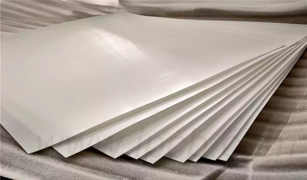
FR4 is formed by high-temperature, high-pressure lamination of epoxy resin and electronic glass fibre cloth. The resin provides insulation and bonding, while the glass fibre delivers structural strength. The significant disparity in their physical properties leads to asynchronous cutting during drilling, which is the root cause of damage.
The drill bit cuts into the FR4 substrate at tens of thousands of revolutions per minute, with the cutting edge exerting shear forces and impact forces on both the resin and glass fibre. The resin has limited heat resistance, causing local friction temperatures to rapidly exceed the glass transition temperature (Tg), resulting in softening, melting, and flow. Upon cooling, this forms resin smear (Smear).
The glass fibres, being highly rigid and brittle, fracture, pull-out, or delaminate under mechanical impact, creating irregularities and micro-cracks on the hole wall. These microscopic defects, when magnified, constitute the industry-concerned hole wall roughness. Furthermore, the interstitial gaps between glass fibre bundles allow copper solution to permeate like a wick absorbing oil during subsequent chemical copper plating and electroplating processes, resulting in the wicking effect.
Hole wall roughness determines copper plating adhesion and uniformity. Rough surfaces cause current concentration, resulting in thin plating, voids, and pinholes, directly compromising metallisation reliability. The wicking effect creates concealed conductive pathways that progressively expand under humid and voltage-biased conditions, triggering leakage currents, short circuits, and interlayer insulation failures. Both issues stem from drilling’s disruption of the FR4 interface structure, making source control more cost-effective and quality-advantageous than remedial measures.
Core Causes and Quantification Standards for Hole Wall Roughness
Hole wall roughness, measured as the arithmetic mean deviation (Ra) of microscopic surface irregularities post-drilling, serves as a quantifiable key metric. IPC standards stipulate clear requirements for different application grades: conventional products require Ra ≤ 1.5μm, while automotive, industrial control, and high-frequency/high-speed boards demand control within Ra ≤ 0.8μm.
The primary factors contributing to FR4 hole wall roughness converge in four dimensions:
Drill Condition
Blunted edges, chipped corners, and wear transform ‘cutting’ into ‘extrusion tearing,’ resulting in prominent glass fibre protrusions and visible resin scratches. Mismatched drill helix angles, point angles, and taper angles with the FR4 substrate exacerbate poor chip evacuation and hole wall abrasion.
Process parameter alignment
Mismatched spindle speed and feed rate are frequent culprits. Low spindle speed coupled with high feed rate yields insufficient cutting force, tearing glass fibres. Excessively slow feed prolongs friction time, intensifying thermal damage. Excessive depth-to-diameter ratio without peck drilling allows chip backflow, causing secondary wall scraping.
Auxiliary Materials and Equipment Precision
Missing or insufficiently thick cover plates cause fibreglass burrs at the entry point. Poor-quality backing plates increase exit burrs and delamination. Excessive spindle runout and unstable pressure feet introduce vibration-induced roughness.
Characteristics of FR4 Substrate Material
Boards with high glass fibre content, low resin flowability, and insufficient curing are more prone to fibre fraying and resin detachment during drilling, inherently resulting in higher surface roughness.
Hole wall roughness is not an isolated issue; it directly increases the difficulty of subsequent deburring and copper plating control, forming the starting point for yield and reliability challenges.
Formation Pathways and Risk Transmission of Wick Effect
The wick effect, also termed capillary action, describes copper plating permeating into the FR4 substrate along micro-fissures within glass fibre bundles. Visually resembling oil absorption through a wick, it constitutes a classic capillary phenomenon. Its formation follows a fixed sequence:
Drilling creates micro-cracks → Resin stripping solution infiltrates through fissures → Chemical copper nucleates within crevices → Electroplated copper progressively fills and extends.
Thermal and mechanical stresses during drilling serve as initiation conditions: high-speed friction softens and displaces resin, causing fibreglass strands to lose confinement and fracture; mechanical impact creates continuous pathways between individual filaments. These fissures are invisible to the naked eye yet sufficiently conductive for liquid penetration.
Wick effect risks exhibit concealment and delayed manifestation:
Mild copper migration reduces interlayer insulation resistance;
Moderate copper migration induces ion migration under high-temperature/humidity conditions, triggering CAF failure;
Severe copper migration may directly cause internal short circuits.
In products operating under prolonged energised conditions—such as automotive, medical, and telecommunications power supplies—wicking is regarded as an ‘invisible reliability killer’. Controlling wicking fundamentally involves eliminating potential fissure formation at the drilling end, followed by sealing residual pathways through subsequent processes.
Systematic Process Solutions for Reducing Hole Wall Roughness
1.Drill Bit Selection and Lifecycle Management
Prioritise ultra-fine-grain tungsten carbide drill bits with precision-ground cutting edges and dense coatings to enhance cutting sharpness and wear resistance. Match drill bit geometry to hole diameter and board thickness: employ high-helix angles for small holes to enhance chip evacuation, and use appropriate point angles for large holes to reduce axial force. Implement drill bit lifespan control, mandating replacement based on hole count and wear condition to prevent blunt bits entering production.
2.Dynamic Optimisation of Drilling Parameters
Adhere to the principle of ‘high spindle speed, adapted feed rate, segmented peck drilling’:
For standard FR4, employ high spindle speeds to ensure cutting efficiency;
Fine-tune feed rate according to hole diameter and depth-to-diameter ratio to prevent tearing from excessive speed or overheating from sluggish feed;
Activate peck drilling for D/L ratios >8:1 to expedite chip evacuation and mitigate secondary scraping;
Optimise retraction speed and dust extraction pressure to maintain bore cleanliness.
3.Standardisation of Auxiliary Materials and Fixtures
Employ aluminium alloy cover plates at entry points to protect hole edges, facilitate heat dissipation, and minimise burr formation; utilise high-density backing plates at exit points to support FR4 substrate material and reduce exit burrs and delamination. Pressure feet distribute force uniformly to prevent panel slippage and vibration.
4.Post-Processing Gentle Treatment
Employ moderate resin removal to eliminate drilling residue without excessive etching of glass fibres. Combine high-pressure water washing with ultrasonic cleaning to remove dust and debris from holes. Where necessary, apply plasma treatment to uniformly activate hole walls and slightly flatten microscopic peaks, reducing roughness without compromising structural integrity.
Post-processing stabilises hole wall Ra values below 0.8μm, meeting premium PCB requirements.
Full Process Control Strategy for Suppressing Wick Effect
1.Drilling Stage: Minimising Microcrack Formation
Optimise parameters to reduce cutting forces and frictional heat, preventing excessive resin softening and glass fibre loosening;
Maintain drill bit sharpness to minimise extrusion and tearing;
Control laminate stack height to ensure uniform stress distribution per sheet, avoiding interlayer misalignment-induced hole wall tearing.
2.Degumming Stage: Prevent Gap Expansion
Degumming is a critical phase in wicking control. Excessive swelling and etching widen glass fibre gaps, exacerbating copper penetration. Adjust chemical concentration, temperature, and duration according to FR4 type to achieve ‘complete residue removal without FR4 substrate damage,’ preserving compact glass fibre bundles.
3.Plating stage: Sealing surface pathways
Optimal plating rates and dispersion capabilities enable copper to preferentially coat hole walls, rapidly sealing surface micro-gaps and preventing copper penetration. Combined with pre-treatment cleaning and activation, this enhances surface coverage uniformity and blocks capillary pathways.
4.Substrate-Design Synergy
Select CAF-resistant FR4 with adequate resin content and thorough curing to reduce cracking propensity at the material level. Design-wise, avoid excessive hole-to-hole spacing and proximity to edges to minimise stress concentration zones.
Through multi-stage coordination, wicking effects can be consistently controlled within IPC Class III standards, meeting high-reliability product requirements.
Drilling damage in FR4 substrates is not uncontrollable; both hole wall roughness and wicking exhibit clear mechanisms of origin and improvement pathways. Grounded in material properties and guided by cutting mechanisms, comprehensive optimisation across the entire chain—from drill bits and parameters to auxiliary materials, equipment, post-processing, and design—enables high-quality drilling with low roughness and no wicking, without compromising efficiency.