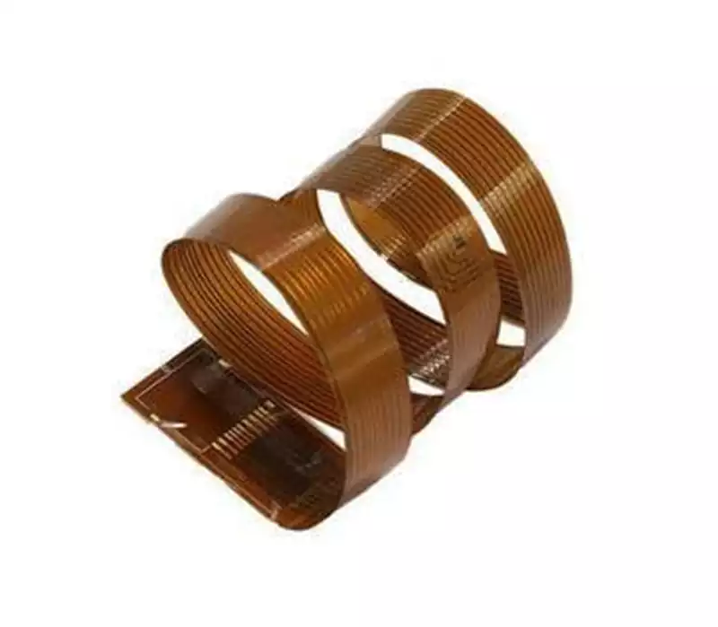
The flexural durability of FPC (Flexible Printed Circuit) is a critical metric for assessing its ability to maintain circuit integrity and electrical conductivity under repeated bending, folding, and mechanical motion. Flexural durability refers to the FPC’s capacity to withstand environmental stresses such as winding, bending, folding, or repetitive motion without circuit breakage, cracking, or significant increases in resistance.
FPCs are extensively used in areas requiring frequent bending, such as smartphone hinges, camera modules, and wearable devices. Consequently, bend resistance directly impacts the reliability and user experience of end products. In high-frequency bending scenarios like foldable smartphones, insufficient bonding strength between copper foil and substrate can lead to fractures after small bending radii and numerous cycles, resulting in conductivity failure.
Impact of Material Selection on FPC Flexural Resistance
Substrate Selection
The substrate is a critical factor determining an FPC’s flexibility and durability. Polyimide (PI) is one of the core materials widely used in FPCs today. As a high-performance polymer, it offers excellent resistance to high and low temperatures, electrical insulation, radiation resistance, and mechanical strength. PI films demonstrate outstanding performance in mechanical properties, dielectric properties, chemical stability, radiation resistance, corrosion resistance, and high/low temperature tolerance, earning it the reputation as a “golden” super-engineering polymer material.
By adjusting the content of rigid diamines in the polymer chain, PI films can simultaneously achieve excellent dimensional stability, high heat resistance, high strength, and good flexibility, making them promising for flexible OLED display applications. PI dielectric materials combine outstanding electrical and mechanical properties with high thermal performance. Compared to polyamide, polyimide typically offers superior mechanical strength. Its robust characteristics enable it to withstand heavy loads and external forces, making it suitable for structural applications where strength and durability are critical. The core material of blue films also incorporates polyimide. However, polyimide exhibits poor flexibility at low temperatures. Additionally, PI resin suffers from low tear strength and high moisture absorption.
PET (polyethylene terephthalate) is another common FPC substrate material, valued for its lower cost. PET material possesses excellent mechanical properties, with impact strength 3 to 5 times that of other films and superior fold resistance. It also exhibits outstanding high and low temperature resistance, operating within a 120°C temperature range. PET plastic has a relatively high melting point, typically between 250-260°C, along with high tensile strength, flexural strength, and impact strength, coupled with good wear resistance and fatigue resistance. Additionally, PET exhibits good thermal stability, weather resistance, chemical resistance, low water absorption, and tolerance to weak acids and organic solvents. However, it is not resistant to hot water immersion or alkaline substances. In aerospace structural materials, PET’s inability to meet stringent requirements for stiffness, temperature resistance, and environmental durability has driven the development of aromatic thermoplastic resin composites. Polyester film composites feature ultra-lightweight, high-strength, multi-layered structures suitable for applications like durable luggage, abrasion-resistant sports equipment, and thermal insulation building materials. PET also finds use in medical devices and consumables, such as medical instrument housings, owing to its heat resistance and electrical insulation properties.
Copper Foil Types
The grain structure of copper foil significantly impacts its bending performance.
Electrolytic Copper (ED Copper): Electrolytic copper foil typically exhibits a vertical columnar grain structure resembling icicles. This coarse crystalline structure results in poor bending resistance, making it prone to fracture during bending. For instance, electrolytic copper (ED copper) with coarse grains tends to fracture after 10,000 bends. Therefore, ED copper is unsuitable for applications requiring high flex life, particularly in fine line designs.
Rolled Copper (RA Copper): Rolled copper foil is produced by repeatedly rolling and annealing high-precision copper strips, typically with thicknesses ranging from 4 to 100 microns. Its grain structure exhibits horizontal layering, resembling a mille-feuille pastry, offering excellent ductility and fatigue resistance. Rolled copper foil achieves elongation rates of 15-40%, enabling greater tensile stress and deformation tolerance, making it the preferred choice for flexible PCBs demanding high bend endurance. Its uniform grain structure enhances resistance to metal fatigue and minimizes deformation accumulation during FPC folding, buckling, and vibration. For optimal bending performance, the bendability of copper alloys depends on the rolling direction of the material. When the bending line is perpendicular to the rolling direction, it is considered Good Way; when parallel, it is Bad Way.
Design Level
Bend Zone Layout
For structures subjected to repeated bending, the ideal approach is to employ a double-sided, fully symmetrical laminate stackup. This means the upper and lower layers share identical material composition and thickness, with the middle layer serving as the symmetry plane. This arrangement positions the neutral axis at the geometric center, enabling uniform distribution of tensile and compressive stresses during bending. Consequently, the stress borne by each individual conductor is minimized.
Trace and Solder Pad Optimization
Teardrop Transitions: Employing teardrop-shaped transitions at trace-to-pad connections significantly enhances joint strength, reducing the risk of pad lifting or breakage during bending.
Copper Pour Strategy: Avoid solid copper pours in bend zones whenever possible. If necessary, use grid-patterned or windowed copper pours to improve flexibility.
Line Width and Spacing: Use uniformly wide, moderate-width traces in bending zones, avoid abrupt width changes, and increase trace spacing appropriately to reduce mutual stress effects.
Staggered and Non-Linear Routing: Avoid placing all traces in a straight line; employ staggered routing or wave/snake patterns to distribute stress concentration.
Prioritize Fine Traces: Where space permits, use finer traces with uniform spacing, as they bend more readily and better withstand repeated deformation.
Arc Transitions: Avoid sharp right-angle turns. All transitions must employ smooth arcs to minimize stress concentration.
Cover Films and Adhesives
Traditional cover films use PI with acrylic or epoxy adhesives. Acrylic adhesives typically offer greater flexibility than epoxy.
Adhesive-Free Substrates
This represents the optimal choice for high-end, bend-resistant applications. Methods like chemical vapor deposition (CVD) deposit PI directly onto copper, completely eliminating the adhesive layer. Adhesive layers are typically rigid and act as weak points during bending; removing them significantly enhances flexibility and reliability.
Reinforced Boards/Stiffeners
For rigid reinforced boards like FR4 used in the printed area, edges must be positioned away from bending zones to smoothly transition stress.
Manufacturing Process
- Controlling Etch Factors
A well-controlled etching process produces conductors with cross-sections close to trapezoidal, rather than mushroom-shaped or concave. Trapezoidal conductors feature smoother edges and reduced stress concentration. - Precise Cover Film Alignment
Ensure cover film windows are precisely aligned, fully covering protected areas with smooth edges. - Surface Treatment Selection
Choose flexible surface treatments. For instance, electroless nickel-gold plating is relatively brittle and may crack under extreme bending. Electroplated soft gold or OSP (Organic Solderability Preservative) may be more suitable, depending on the application. - Avoid contamination. Any contamination during manufacturing, especially particulate residue in bend zones, creates stress points leading to premature failure.
Future Trends and Challenges
Trends
Continuous technological advancements will unlock new opportunities for enhancing FPC bend resistance. On one hand, developments in materials science will provide more high-performance material options for FPCs. For instance, novel nanomaterials and composites with superior physical and chemical properties hold promise for enhancing FPC flexibility, fatigue resistance, and corrosion resistance. On the other hand, continuous innovation in manufacturing processes will drive FPC toward higher precision and reliability. The application of advanced techniques like laser direct imaging and nanoimprinting will enable finer circuit processing and increased production efficiency.
Furthermore, with the rapid advancement of technologies like the Internet of Things and artificial intelligence, FPC application domains will continue to expand. Beyond traditional consumer electronics, FPC will play a significant role in automotive electronics, aerospace, and medical electronics. In these high-end application areas, demands for FPC’s fold resistance, reliability, and performance will be even higher, driving continuous technological innovation and product upgrades within the FPC industry.
Challenges Faced
However, FPC also faces certain challenges in enhancing fold resistance. First, the high cost of high-performance materials limits their widespread adoption. Balancing cost reduction with performance maintenance remains a critical challenge for the industry. Second, as FPCs enter increasingly complex operating environments, their environmental resistance must be enhanced. For instance, in automotive electronics, FPCs must withstand extreme conditions like high temperatures, humidity, and vibration. In aerospace applications, FPCs must possess special properties like radiation resistance and tolerance to extreme temperatures. Enhancing FPC environmental resilience represents a significant current challenge.
Additionally, the manufacturing process for FPCs is complex, making quality control during production challenging. Issues arising at any stage can lead to degraded performance or failure of the FPC. Therefore, establishing a robust quality control system to ensure the production quality and reliability of FPCs is also a key concern for the FPC industry.
