Overview and Basic Concepts of Flex PCB Prototypes
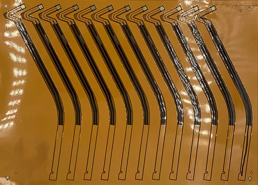
In modern electronics design and manufacturing, flex PCB prototypes (flexible printed circuit board prototypes) have become an essential component of innovative product development. Compared to traditional rigid PCBs, flexible PCBs offer advantages such as flexibility, lightness, vibration resistance, and the ability to accommodate three-dimensional layouts. This has led to their widespread application in consumer electronics, wearable devices, medical devices, and aerospace. Prototyping not only verifies product functionality but also directly impacts the performance, reliability, and cost control of mass-produced PCBs. Therefore, understanding the concept, characteristics, and application scenarios of flex PCB prototypes is essential for engineers and procurement personnel to make sound design decisions.

Flex PCB prototypes typically include single-, double-, or multi-layer designs. Their core concept is to implement circuit functionality using flexible materials (such as polyimide or polyester film) to support conductive traces, combined with a precise copper deposition process. Compared to mass-produced PCBs, the prototype stage prioritizes verifying electrical performance, mechanical properties, and design feasibility, rather than optimizing the costs of mass production. Therefore, flex PCB prototypes are not only a design tool but also a crucial bridge between technology verification and innovative iteration.
Furthermore, flexible PCB prototype design requires consideration of factors such as bend radius, conductor routing, interlayer insulation, heat dissipation, and surface treatment, all of which directly impact reliability in practical applications. For example, in wearable devices, flexible PCBs must withstand repeated bending without conductor breakage; in medical devices, flexible PCBs must ensure stable electrical performance even in high-humidity environments. Therefore, prototyping requires not only electrical engineering knowledge but also a comprehensive understanding of materials science, mechanics, and manufacturing processes.
In summary, flex PCB prototypes are a critical step in the transition from concept to production of modern electronic products, carrying the core mission of design verification, functional testing, and innovative experimentation. Only by fully considering material properties, structural design, and manufacturing processes during the prototyping stage can the final product achieve optimal performance, reliability, and cost.
Key Points in Material and Structural Design for Flex PCB Prototypes
In flexible PCB prototype design, material selection and structural design are key factors in ensuring electrical performance, mechanical strength, and long-term reliability. Unlike rigid PCBs, flexible PCBs must be flexible, fold-resistant, lightweight, and provide reliable insulation while also carrying circuitry. Therefore, the rationality of the material and structural design directly impacts the success of prototypes and the feasibility of mass production.
Substrate Selection
Flexible PCB substrates primarily come in two types: polyimide (PI) and polyester film (PET):
Polyimide (PI): Offers excellent high-temperature resistance, mechanical strength, and chemical stability, making it suitable for high-performance electronics and demanding industrial applications. PI substrate can withstand reflow soldering temperatures while maintaining flexibility, making it a preferred choice for high-end wearables and avionics.
Polyester film (PET): Offers lower cost and excellent flexibility, but suffers from lower high-temperature resistance and mechanical strength than PI. It is suitable for low-cost or disposable product prototypes, such as consumer electronics devices undergoing short-term verification.
The material thickness typically ranges from 25 to 125 microns. Thinner thickness improves flexibility, but reduces circuit-carrying capacity and mechanical strength. Therefore, a balance between flexibility and strength must be struck during design.
Copper Foil and Conductor Design
Flexible PCB prototypes typically use copper foil for their conductive layers, with a common thickness of 935 microns (1/41 oz). During the prototype stage, the following factors should be considered when selecting copper foil thickness:
Current Carrying Capacity: Thicker copper can handle higher currents, but increases rigidity and cost.
Flexibility: Excessively thick copper can affect the PCB’s bendability and reliability.
Manufacturing Process Compatibility: Copper thickness must be compatible with the etching and plating processes to ensure clear and uniform traces.
In addition, conductor routing design must consider bending stress and signal integrity. When a flexible PCB is folded or bent, conductors experience compression on the inside and tension on the outside. Therefore, critical conductors should have an appropriate bend radius and avoid high-stress areas to prevent breakage or signal distortion.
Layer Structure and Stackup Design
Flexible PCB prototypes can be designed with single, double, or multiple layers:
Single-layer: Simple structure, suitable for low-complexity circuit prototypes, facilitating rapid functional verification. Two-layer: Increases signal integrity and power plane routing capabilities, suitable for medium-complexity products.
Multi-layer flexible PCB: Allows for complex circuit routing and high-density designs, but carries higher manufacturing costs and difficulty. It is suitable for high-end prototypes or high-frequency signal transmission.
In stackup design, the choice of insulation layer material and thickness is crucial. It must ensure electrical isolation and mechanical flexibility between layers, while also balancing heat dissipation and voltage resistance.
Surface Treatment and Protective Layers
To improve soldering reliability and prevent oxidation, flexible PCB prototypes typically require surface treatments such as ENIG, OSP, or metallization. Furthermore, flexible PCBs often use coverlays instead of the solder mask used in rigid PCBs to protect traces and pads while maintaining flexibility. The choice and application of coverlays must be compatible with the copper foil thickness, soldering process, and bending stress; otherwise, cracking or delamination may occur.
Mechanical Properties and Bendability
Bend radius, number of folds, and mechanical fatigue life must be considered in prototype design:
Excessively small bend radiuses can lead to copper breakage or insulation cracking. The more folds, the higher the stress on the materials and conductors, necessitating experimental verification of prototype reliability.
For complex three-dimensional layouts, strategic planning of fold locations is necessary to avoid concentrated stress.
By carefully selecting materials, copper foil, laminate structure, and surface treatment, combined with mechanical simulation and bend testing, we can ensure that flex PCB prototypes not only meet electrical performance requirements during the prototype verification phase but also withstand the bending and handling demands of real-world applications.
Key Points in Manufacturing and Processing of Flex PCB Prototypes
Flex PCB prototype manufacturing not only determines electrical performance and reliability but also impacts the feasibility of transitioning from prototype verification to mass production. Therefore, mastering the key process steps for flexible PCBs is an essential skill for engineers and procurement personnel in prototyping.
Copper Foil Lamination and Lamination Process
The first step in manufacturing a flexible PCB prototype is to laminate the copper foil onto the flexible substrate to form a processable circuit layer:
Lamination Method: Typically, heat pressing or gluing is used to evenly adhere the copper foil to the polyimide or polyester film substrate. The hot pressing process ensures a strong bond between the copper foil and the substrate, improving peel resistance.
Critical Control Points: Temperature, pressure, and time require precise control to prevent blistering, wrinkling, or uneven adhesion of the copper foil. Consistency in small batches is particularly important during the prototype stage.
Pattern Etching and Circuit Processing
The laminated copper layer is etched to form the circuit pattern:
Photolithography: A photoresist film is applied to the copper foil surface and exposed to UV light to form the circuit pattern. The accuracy of the photolithography directly determines the accuracy of the prototype’s circuit width and spacing.
Chemical Etching: An acidic or alkaline solution is used to remove the unprotected copper foil and form the desired circuit. Controlling the etching time and concentration is crucial; otherwise, uneven line widths or residual copper foil can occur.
Precision Requirements: Prototype PCBs are often used to verify high-density circuits. Etching accuracy is crucial for high-frequency signal integrity and bending stress distribution.
Drilling and Interlayer Connections
For multilayer flexible PCB prototypes, vias (VIAs) are crucial for achieving electrical connections between layers:
Laser drilling: Used for producing vias with tiny diameters, suitable for high-density designs. Laser drilling ensures consistent hole diameters and smooth hole walls, reducing resistance and soldering risks.
Mechanical drilling: Suitable for larger hole diameters, but prone to stress concentration, requiring strategic placement of bends to minimize mechanical damage.
Copper plating: Copper plating on the hole walls creates reliable interlayer connections and is a crucial step in prototyping electrical performance verification.
Surface Treatment and Protective Film Covering
Prototype PCBs often require protection for copper traces and improved soldering reliability:
Coverlay: A coverlay unique to flexible PCBs replaces the solder mask used in rigid PCBs, protecting copper traces from oxidation and mechanical wear while maintaining flexibility.
Surface treatment technologies: Common options include ENIG (electroless nickel-gold plating) and OSP (organic overcoat). The choice depends on the soldering process and prototype testing requirements.
Depaneling, Bending, and Mechanical Verification
After prototype manufacturing is complete, depaneling and mechanical performance verification are required:
Depaneling process: V-cut or laser cutting is typically used to ensure neat board edges and protect circuitry.
Bending test: By testing the bending, number of bends, and bend radius in simulated real-world environments, the durability of the flexible PCB is verified.
Stress analysis: For complex 3D layouts, simulation software can be used during the prototype phase to predict stress concentration areas and optimize bend locations and trace layout.
Key Process Summary
During the prototype phase, the accuracy and consistency of the manufacturing process directly determine the final test results and mass production feasibility.
Control copper foil lamination, etching accuracy, and hole copper plating quality to ensure reliable electrical performance.
Appropriately select coverlay materials and methods to balance protection and flexibility.
Verify bend radius and mechanical fatigue life to provide reference for mass production design.
Through scientific and rational process design and operation, the flex PCB prototype not only truly reflects the design performance but also provides valuable data and optimization directions for subsequent mass production.
Testing and Verification Methods for Flex PCB Prototypes
During the flexible PCB prototype stage, testing and verification are critical steps to ensure design feasibility and performance reliability. Through systematic testing, potential issues can be identified, designs can be optimized, and a reliable basis for mass production can be provided.
Electrical Performance Testing
Electrical testing is the most direct method for verifying the functionality of flexible PCB prototypes. It includes the following aspects:
Impedance Testing: High-frequency signal transmission requires stable line impedance. During the prototype stage, an impedance analyzer is used to measure the impedance of specific lines to ensure signal integrity.
Continuity and Short Circuit Testing: Flying probe testing or in-circuit test equipment is used to check line continuity to ensure there are no open or short circuits.
High-voltage and Insulation Testing: High-voltage testing verifies the insulation strength between layers to prevent breakdown or leakage risks in multi-layer designs.
Current Carrying Capacity Testing: Current-carrying capacity testing is performed on critical power supply lines to ensure that they will not overheat or damage the conductors under actual operating conditions.
Mechanical Reliability Testing
Since flexible PCBs are frequently bent during use, mechanical performance testing is particularly important:
Bend Testing: By setting the bend radius and number of bends, the PCB’s folding durability is evaluated to prevent copper wire breakage or insulation cracking.
Vibration and Shock Testing: Simulates the mechanical stresses found in actual use environments to verify the PCB’s reliability under vibration and shock.
Tension and Compression Testing: Evaluates the PCB’s electrical conductivity and structural integrity under tension or compression, particularly useful for wearable devices or dynamic applications.
Thermal Performance and Environmental Adaptability Testing
The performance stability of flexible PCB prototypes under varying temperature and humidity conditions is a key focus of design verification:
Temperature Cycling Testing: Simulates alternating high and low temperature environments to test the PCB’s thermal expansion, contraction, and conductor stress response.
High-Temperature Aging Testing: Tests the PCB’s material stability and electrical performance under prolonged high-temperature conditions to predict its lifespan in mass production.
Damp Heat Testing: Tests the water resistance of the insulation layer and copper foil in a high-humidity environment to ensure reliable operation in humid environments.
3D Layout and Folding Verification
Flexible PCBs with complex 3D layouts require special verification:
Fold/Curl Testing: Simulates the actual folding of the product to check whether the circuitry is subjected to excessive stress.
Stress Monitoring at Critical Locations: Monitors the stress distribution at folding points using stress sensors or optical inspection technology, providing data support for design optimization.
Functional Verification and Prototype Iteration
Testing is not limited to individual indicators; overall functional verification is also required:
Circuit Functional Testing: Ensures that the prototype functions properly when connected to external devices or loads.
Signal Integrity Verification: Verifies that high-frequency signal transmission meets design requirements to avoid interference or attenuation issues.
Iterative Optimization: Based on test results, parameters such as copper trace width, bend radius, and coverlay thickness are adjusted, and multiple prototype iterations are performed until design goals are met.
Through systematic testing and verification, flex PCB prototypes not only identify potential design flaws but also provide optimization guidance for subsequent mass production, ensuring product stability, reliability, and high performance in real-world applications.
Analysis of Application Scenarios and Advantages of Flex PCB Prototypes
Flexible PCB prototypes are not only crucial for engineering verification, but their diverse application scenarios also fully demonstrate their design value and technical advantages. Specific application cases clearly demonstrate the unique role of flexible PCBs in modern electronic products.
Consumer Electronics
Flexible PCB prototypes are widely used in consumer electronics such as smartphones, tablets, and wearable devices:
Thinness and Bendability: Flexible PCBs enable three-dimensional wiring, tightly integrating electronic components within limited space, meeting the demand for thinner and lighter devices.
Rapid Prototyping: During the product development phase, flexible PCB prototypes allow for rapid verification of circuit layout and functionality, shortening the design cycle.
High Reliability: Flexible PCBs’ flex durability and high-density design enable devices to withstand repeated folding and mechanical stress during daily use.
Medical Devices
Flexible PCBs offer unique advantages in medical devices:
Wearable medical devices, such as heart rate monitors and blood oxygen monitors, can conform to the body’s curves for a comfortable fit. High Reliability and Environmental Resistance: Medical devices have stringent requirements for electrical performance and safety. Flexible PCB prototypes undergo heat and humidity cycling, flexing, and electrical testing to ensure reliable mass-produced products.
Miniaturization Design: The prototype stage can verify the feasibility of complex circuits within limited spaces, laying the foundation for miniaturized medical electronics.
Industrial Control and Automotive Electronics
In the industrial control and automotive electronics fields, flexible PCB prototypes are used in high-temperature, high-vibration, and high-frequency signal scenarios:
High-Temperature Tolerance: PI-based flexible PCBs can withstand high-temperature environments and are suitable for use within automotive engine compartments or industrial equipment.
Vibration and Shock Resistance: Flexing tests and vibration verification ensure reliable PCB operation in harsh environments.
Complex Routing Capabilities: Multi-layer flexible PCB prototypes enable High-density wiring supports the integration of automation control, sensors, and signal processing modules.
Aerospace and High-end Electronics
Flexible PCB prototypes demonstrate cutting-edge technological value in the aerospace and high-end electronics sectors:
3D Layout and Space Optimization: Prototyping verifies complex 3D wiring designs, enabling compact integration of spacecraft or satellite equipment.
Radiation Resistance and Extreme Environment Adaptability: Flexible PCB prototypes can meet the requirements of low-temperature, high-radiation, and high-vibration environments through material selection and process verification.
Fast Iteration and Customization: The prototype stage allows for multiple design adjustments, enabling customized and optimized production, providing reliable support for high-end applications.
Advantage Summary
Based on application scenario analysis, flex PCB prototypes demonstrate the following core advantages:
Design Flexibility: Bendable, foldable, and capable of 3D layouts meet complex product requirements.
Fast Verification and Iteration: The prototype stage enables rapid design verification, shortening R&D cycles and reducing mass production risks.
High Reliability: Electrical, mechanical, and environmental testing ensures product stability and durability in real-world applications. Space and Weight Optimization: Suitable for thin, lightweight, and compact devices, achieving product miniaturization and portability.
Overall, flexible PCB prototypes are not only an important tool for product development but also a key means of achieving high performance, high reliability, and innovative designs in modern electronic products.
Future Trends and Development Directions of Flex PCB Prototypes
As electronic products evolve towards thinner, lighter, higher-performance, and smarter designs, the technological innovation and application potential of flex PCB prototypes are also showing multi-dimensional development trends. Understanding these trends not only helps design more efficient prototypes but also provides a reference for companies planning for future markets.
High Density and Miniaturization
Future flexible PCB designs will develop towards higher density and miniaturization:
Fine Circuit and Microvia Technology: Through more sophisticated etching and laser drilling techniques, high-density wiring can be achieved to meet the needs of miniature wearable devices and medical electronics.
Multi-layer Stacking Design: Increasing the number of circuit layers optimizes signal transmission and power management while maintaining a balance between flexibility and bendability.
The Importance of Prototype Verification: In high-density designs, verification during the prototype stage can promptly identify signal interference, thermal management, and mechanical stress issues, providing reliable data for mass production.
Material Innovation and Functional Integration
Advances in materials technology will drive the multifunctional integration of flexible PCBs:
New high-performance substrates: Materials such as ultra-thin polyimide and liquid crystal polymer (LCP) offer improved temperature, humidity, and radiation resistance.
Conductive Material Innovation: The application of highly conductive copper foil, silver nanowires, and flexible conductive inks enhances electrical performance and bendability.
Functional Integration: Sensors, antennas, and microcomponents can be integrated onto flexible PCBs to achieve functional verification during the prototype stage, providing a viable solution for smart wearables and IoT devices.
Intelligent Manufacturing Processes
Prototype manufacturing will incorporate intelligent technologies to improve precision and efficiency:
Automated processing equipment: Laser etching, precision copper plating, and automated bend detection equipment enhance prototype manufacturing consistency.
Digital Design Verification: Using simulation software and digital twin technology, flexible PCBs can be virtually verified for electrical performance, thermal stress, and bending stress, reducing the number of physical iterations.
Rapid Prototyping: Incorporating additive manufacturing technology accelerates the flexible PCB design and functional verification cycle.
Expanding Wearable and Smart Applications
The application of flexible PCB prototypes in wearable devices, medical electronics, and the smart IoT will continue to expand:
Body Conformability and Dynamic Adaptability: Testing the folding and stretching properties of flexible PCBs during the prototype phase ensures comfort and reliability for wearable devices.
Environmental Adaptability Verification: Simulating actual operating environments during the prototype phase to verify water resistance, heat resistance, and chemical corrosion resistance, ensuring product mass production.
Intelligent Function Expansion: Flexible PCBs can integrate sensors, microcontrollers, and wireless communication modules to enable prototype verification of multifunctional smart devices.
Sustainability and Green Manufacturing
Future development of flexible PCB prototypes will also focus on environmental protection and sustainable manufacturing:
Low-Pollution Materials and Processes: Selecting environmentally friendly substrates and green chemical etching processes reduces environmental impact.
Recyclable and degradable design: Developing recyclable copper foil and degradable polymer materials to achieve environmentally friendly upgrades for prototype and mass-produced PCBs.
Energy-saving production: Optimizing the prototype manufacturing process to reduce energy consumption and material waste, providing technical support for sustainable business development.
Trend Summary
In summary, the future development direction of flex PCB prototypes presents the following characteristics:
Technologically, higher density, miniaturization, and intelligence are expected; materials pursue high performance, lightweightness, and environmental friendliness; manufacturing incorporates automation and digitalization to improve prototype verification efficiency; applications expand to wearables, medical, IoT, and high-end industrial fields; and sustainability becomes a key consideration in design and manufacturing.
Flexible PCB prototypes are not only a core component of electronic product development but also a key technological bridge for promoting innovation, optimizing design, and exploring future applications. Understanding future trends helps engineers and companies plan ahead during the prototyping stage, laying the foundation for mass production and market competition.
Summary
As a crucial step in modern electronic product development, flex PCB prototypes integrate material selection, structural design, precision manufacturing, rigorous testing, and functional verification, providing reliable support for products from concept to mass production. Through scientific design and process control, prototypes not only ensure electrical performance, mechanical reliability, and environmental adaptability, but also enable rapid verification and optimization in a variety of fields, including consumer electronics, medical devices, automotive electronics, and aerospace. In the future, with the development of high-density, miniaturized, intelligent, and environmentally friendly manufacturing, flexible PCB prototypes will continue to drive electronic product innovation, providing engineers and companies with more efficient, reliable, and forward-looking solutions during the R&D and mass production stages. Mastering the entire prototype design and verification process is key to ensuring product success and the implementation of innovation.


