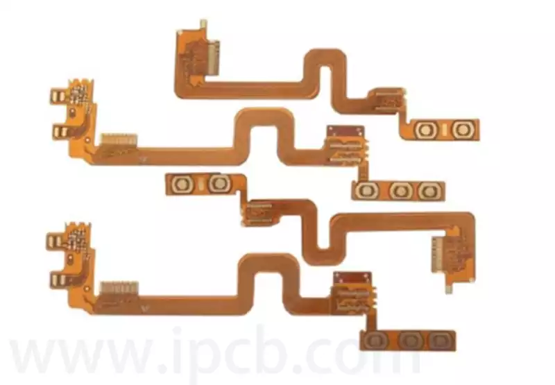
The flex pcb thickness varies depending on the material, manufacturing process and application requirements, typically ranging from 0.1mm to 1.6mm. Choosing the right thickness is critical to ensure product performance and longevity.
Factors affecting the flex pcb thickness
- Material Selection: Flexible boards usually use flexible materials such as polyimide (PI) or polyester (PET) as the substrate. The thickness and characteristics of these materials will directly affect the overall thickness of the flexible board.
- Manufacturing process: the manufacturing process of flexible boards, such as pressing. Etching and other process steps will also have an impact on the thickness of the board. In addition, the thickness of copper foil and the number of layers is also a key factor in determining the thickness of the flexible board.
- Application requirements: different electronic products have different requirements for the thickness of the flexible board. For example, some products that require highly integrated and thin and light designs may choose thinner flexible boards, while some products that need to withstand greater mechanical stress may require thicker flexible boards.
Flex pcb thickness in different applications
- In the field of consumer electronics, such as tablet PCs and Bluetooth headsets, due to the pursuit of the ultimate thin and light, the thickness of Gemini’s FPCs is mostly concentrated at 0.1mm to 0.3mm. Bluetooth headset, FPC needs to connect the battery. Sound unit and control chip, its thickness directly affects the wearing comfort and product volume.
- In the field of automotive electronics, considering the complex use of the environment, flex pcb thickness increased to 0.3 mm to 0.6 mm, in order to enhance the structural strength and durability, such as the centre control display behind the FPC,need to withstand a variety of conditions in the car driving.
- In the field of industrial automation, large-scale equipment in the flex pcb thickness of up to 0.5 mm or more to meet the multi-signal transmission. High durability and long-term wear resistance needs. In such applications, stability and reliability take precedence over thinness and lightness.
Flex pcbs are classified as single layer, double layer, multilayer and rigid flex boards.Basic methods for calculating the thickness of flexible circuit boards.
(1)Single FPC
The structure of single-layer flexible circuit board is as follows:
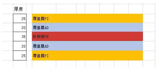
Single-sided flex pcb thickness: 25um + 20um + 35um + 20um + 25um = 125um = 0.12mm
Note: The thickness of the adhesive varies according to the thickness of the copper, for 112, 1/30ZCu, we usually use 12um adhesive. But for 10Z Cu, we have to use 20um adhesive, which is based on the general material. If we want to make the board thinner, we can also use non-glue material to make the board thickness about 0.8mm thickness.
(2)Double-sided FPC
Double-sided FPC flexible circuit board indicates that there are two layers of alignment in the FPC. The structure of double-sided FPC is as follows:
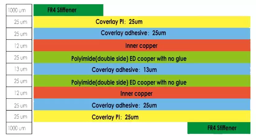
Double-sided flex pcb thickness 25um + 25um + 12um + 25um + 13um + 25um + 12um + 25um + 25um = 187um = 0.19mm Note: Usually there are FPC flexible circuit boards need to be reinforced, the reinforcement of FR4, P1, adhesive paper, PET, electromagnetic film, steel and aluminium sheet reinforcement.Need to reinforce the FPC in the calculation of thickness is added to the thickness of the reinforcement is OK.
Selection of flex pcb thickness of the key factors
- Application requirements and space constraints
Flexible circuit boards are often used in electronic devices that require thinness and compactness, such as smartphones, wearable devices and automotive electronics. Thinner FPCs (usually between 0.1mm and 1.0mm) help save space and reduce weight, and are suitable for tight spaces and complex curved layout scenarios. - Mechanical Strength and Flexibility
Thinner thickness FPCs offer better bending performance and flexibility, suitable for products with multiple dynamic bending requirements. While thicker boards provide higher mechanical strength and support, can withstand greater current load and higher voltage, suitable for carrying heavier components and higher voltage applications. - Material and layer structure
The flex pcb thickness consists of the base material (generally polyimide PI or polyester PET), copper foil thickness, cover film and reinforcement layer. The thickness of the base material is commonly 0.05mm, 0.075mm and 0.1mm, etc., the thickness of the copper foil is usually in the range of 17 to 70 microns, and the thickness of the reinforcing layer is customised according to the demand, commonly ranging from 0.075mm to 0.25mm. - Electrical Performance Requirements
The flex pcb thickness affects its insulation and voltage tolerance.Thicker flexible circuit boards usually provide better insulation and can withstand higher voltages, as well as improved heat resistance and durability.
The design needs to take into account the electrical parameters to choose the right thickness to prevent electrical failures.
- Cost and Manufacturing Process
The greater the thickness, the more material is used, the higher the cost, and the more difficult the manufacturing process may be. Using standard thicknesses reduces manufacturing lead times and costs, while special thicknesses may present additional costs and process challenges.
Reasonable selection of the flex pcb thickness needs to be a combination of material properties, manufacturing processes and specific application requirements. Under the premise of ensuring performance and reliability, optimising thickness not only improves product quality, but also effectively controls costs and achieves the best balance between thinness and durability.