In PCB (Printed Circuit Board) design, the connection method is a very important part. It determines the reliability, performance and functionality of electronic devices. But how to connect pcb board?
PCB board connection methods mainly include V-cut, stamp holes, hollow connecting strips, V-cut, copper foil bridge connection, separated connecting boards, panelization and so on.
V-cut is a common PCB board connection method. It realizes the connection between circuits by cutting a V-shaped groove between two layers of circuits.The advantages of V-cut are reliable connection, compact layout, and suitable for high-density printed circuit boards.
When using the V-cut connection method, you need to pay attention to the following points:
- The width and depth of the V-cut groove should be designed according to the requirements of the circuit board to ensure connection reliability and electrical performance.
- The length of the V-cut groove should be designed according to the length requirement of the corresponding circuit to be connected to ensure the quality of signal transmission.
- The shape of the V-cut groove can be adjusted according to specific design requirements, such as V-type, U-type or other shapes, but to maintain consistency.
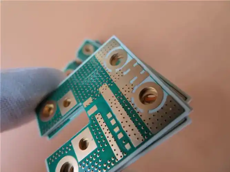
Stamp hole is a commonly used PCB board connection method.It realizes the connection between circuits by punching holes in the board and then by soldering or inserting connectors. The advantages of stamp holes are that they are simple in structure, easy to fabricate,and suitable for low to medium density printed circuit boards.
When using the stamp hole connection method, you need to pay attention to the following points:
- The size and shape of the stamp holes should be designed according to the requirements of connecting the corresponding circuits to ensure the reliability and electrical performance of the connection.
- The arrangement of the stamp holes should be designed according to the layout requirements of the circuit board to facilitate the installation and connection of the connector.
- The number of stamp holes should be determined according to the number of connections required by the circuit board to avoid redundancy or insufficiency.
Hollow connecting strip is a relatively special way of connecting printed circuit boards. It realizes the connection between circuits by cutting slots in the circuit board and then filling the slots with conductive materials. The advantages of hollow connecting strip are compact structure, reliable connection, suitable for high-density printed circuit board.
When using the hollow connection strip connection method, you need to pay attention to the following points:
- The slot width and depth of the hollow connection strip should be designed according to the requirements of the circuit board to ensure connection reliability and electrical properties.
- The width and length of the hollow connecting strips should be designed according to the size requirements of the connected corresponding circuits to ensure the quality of signal transmission.
- The conductive material of the hollow connecting strip should be selected as suitable material and good connection should be ensured in the filling process.
Soldering method
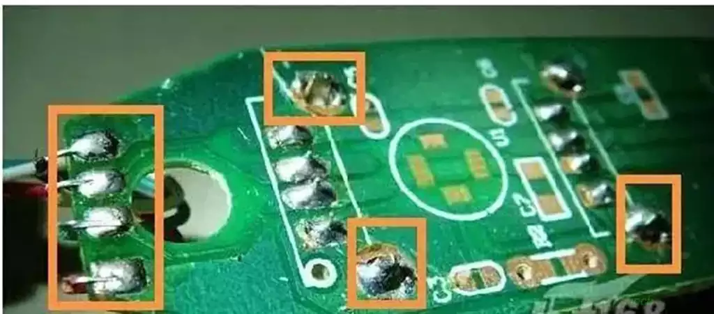
Soldering is one of the most common ways to interconnect PCB boards, which connects the pins of electronic components to the pads on the PCB substrate through molten solder. Soldering is simple, inexpensive, highly reliable, and can effectively avoid poor contact failures. However, the interconnection point after welding is relatively inconvenient to interchange and repair.
①PCB wire soldering
Directly through the wire will be connected to the external PCB board and the board outside the components or other parts of the welding together, applicable to the external lead less parts.
② PCB line welding
The use of wires to connect the two PCB boards, the connection is reliable and not easy to error, applicable to the relative position of the PCB board is not restricted.
③Direct welding between PCBs
Direct welding between two PCB boards, commonly used in 90-degree angle connection, after the connection to form a whole PCB parts.
For external connections, there are mainly the following:
- Wire welding
With the wire PCB printed circuit board on the external connection point with the board outside the components or other parts can be welded directly, without any connector. - Line welding
This method is commonly used between two boards for the 90-degree angle of the connection, the connection becomes a whole PCB printed circuit board components. - Printed board socket
In the more complex instruments and equipment, often use this connection. From the edge of the PCB printed board to make a printed plug, plug part of the size of the socket, the number of contacts, contact distance, positioning holes in the location of the design, so that it matches the special PCB printed board socket. - Standard pin connection
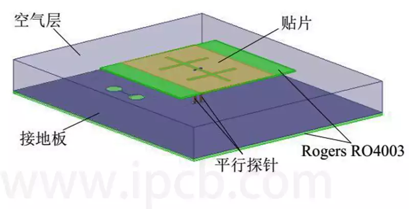
This method is suitable for use in small instruments, through the standard pins will be connected to two pieces of printed circuit boards, two pieces of printed circuit boards are generally parallel or perpendicular.
Connect pcb board technology is diverse and critical, reasonable choice and application, to ensure a solid and efficient connection, to promote the performance of electronic equipment.