Circuit board cutting refers to the separation of a circuit board into two or several pieces according to a reasonable line without affecting its effectiveness. Common circuit board cutting methods include straight line cutting (V-cutting), milling cutting, wire cutting and laser cutting. Each of these cutting methods has its own characteristics, and the choice depends on the design requirements of the PCB, the cost and the availability of production equipment.
how to cut a circuit board:Methods of cutting circuit boards
- Straight line cutting (V-cut): This is the most commonly used means of cutting. By using a cutting device or a V-shaped blade, a straight cut is made along the edge of the PCB board or a preset cutting line to obtain the desired size and shape.
- Milling and Cutting: For PCB boards that require more precise shapes and hole positions, milling and cutting are usually performed using CNC milling machines. According to the design documents, rotary tools are utilized to remove the excess parts of the PCB board to achieve the desired shape and size.
- Wire Cutting: Some complex PCB boards may require internal or complex curve cutting. In this regard, wire cutting technology can be used to cut PCB along a predetermined path by means of a high-speed fine wire cutter. Wire cutting can be realized with high precision and complexity.
- Laser Cutting: Laser cutting is a non-contact cutting technology that enables high precision and complex shapes to be cut. By utilizing the thermal energy of the laser beam, the material on the PCB is vaporized or melted to achieve the desired shape cut.
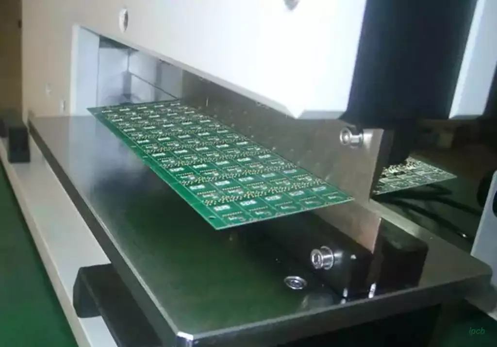
V-Shape Cutting Method
V-cutting is a set of pre-cut demarcation lines at specific locations on the PCB using a rotary cutting tool according to the requirements of the drawing. Its purpose is to facilitate the subsequent assembly of SMT circuit boards for De panels.
The reason for designing the V-Cut on the circuit board is that the circuit board itself has a certain degree of strength and rigidity. The pre-cut V-Cut circuit facilitates the operator to smoothly cut the original panel into one board.
First of all, the V-Cut can only cut straight lines and a single cut can only go through to the bottom. In other words, the V-Cut can only cut a straight line from end to end. It cannot turn or change direction, nor can it jump a short distance like a sewing thread. This is because the V-Cut’s notch is cut using a chainsaw with two discs at the top and bottom, and because PCB cutting requires such a high degree of precision (in millimeters) that it’s impossible to cut only halfway and then retract the tool.
Secondly, if the thickness of the PCB substrate is too thin, it is not suitable for making V-cut notches. Typically, if the board thickness is less than 1.0mm, it is not recommended to make a V-notch because a V-notch would compromise the structural strength of the original PCB. When heavy parts are placed on a board with a V-cut design, the board will tend to bend due to gravity, which is very detrimental to SMT soldering operations (easily leading to empty or shorted solder).
In addition, when the PCB passes through the high temperatures of a reflow oven, the board itself softens and deforms due to the high temperatures above the glass transition temperature (Tg). If the V-cut position and notch depth are not properly designed, the deformation of the PCB will be even worse, which is not conducive to the secondary reflow process.
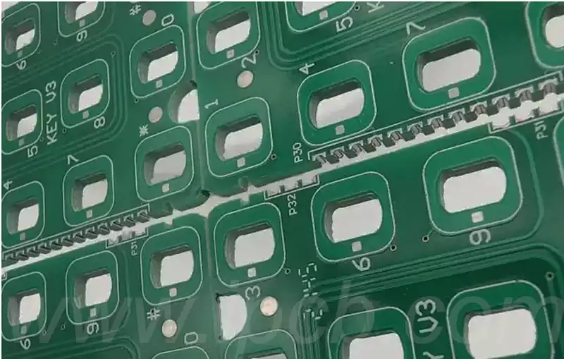
Punch Connection
Generally, PCBs are V-cut, and punching is used only when irregular or round boards are encountered. The boards (or empty boards) are joined by punching holes to provide support and prevent them from falling apart. If the mold is opened, it will not collapse. The most common method is to use them to create PCB-independent modules, such as Wi-Fi, Bluetooth, or core board modules, and then use them as separate components placed on another board during PCB assembly.
In mass production, V-cutting is primarily used to split an entire PCB board to increase productivity and reduce costs.
