With the rapid development of power electronics technology, high-voltage circuits—thanks to their high efficiency and stability—have been widely adopted in new energy vehicles, industrial power supplies, and power systems, among many other fields. However, during operation, high-voltage circuits are exposed to severe challenges such as high voltage, strong electric fields, elevated temperatures, and complex environmental conditions. These factors impose extremely stringent requirements on FR4, the core substrate material. Precisely selecting the appropriate FR4 material has therefore become a critical factor in ensuring the safe and stable operation of high-voltage circuits.
Rigidity Requirements of High-Voltage Circuits for FR4
1.Insulation Performance
Insulation performance is the core requirement for FR4 used in high-voltage circuits, as it directly determines the circuit’s ability to withstand dielectric breakdown under high electric fields. The key parameter characterizing insulation performance is dielectric strength, defined as the maximum electric field intensity a material can withstand before breakdown, typically expressed in kV/mm. For high-voltage circuits, higher dielectric strength translates into stronger resistance to high-voltage breakdown.
Conventional FR4 materials exhibit dielectric strength in the range of approximately 18–22 kV/mm and are suitable for low- to medium-voltage applications below 1 kV. In contrast, high-voltage circuits operating between 1 kV and 10 kV require FR4 with dielectric strength of at least 25 kV/mm, while certain high-voltage power equipment may demand dielectric strength of 30 kV/mm or higher. It should be noted that dielectric strength is not “the higher, the better,” but rather must match the circuit’s operating voltage. As voltage levels increase, the requirements for dielectric strength become more stringent. In addition, dielectric strength is influenced by substrate thickness: greater thickness improves overall voltage withstand capability but also increases PCB size and weight, necessitating a careful design trade-off.
2.Resistance to Electrical Tracking
During long-term operation of high-voltage circuits, dust, moisture, and contaminants may accumulate on the PCB surface, forming conductive paths that lead to partial discharges—commonly referred to as electrical tracking. Electrical tracking gradually degrades the insulating layer on the FR4 surface and can ultimately result in short-circuit failures. The primary metric for evaluating tracking resistance is the Comparative Tracking Index (CTI). According to IEC 60112, higher CTI values indicate better resistance to electrical tracking.
FR4 materials are generally classified into three CTI levels:
CTI ≥ 600 V (Group 1): Suitable for high-voltage and highly polluted environments.
400 V ≤ CTI < 600 V (Group 2): Suitable for medium- to high-voltage applications in relatively clean environments.
175 V ≤ CTI < 400 V (Group 3): Suitable only for low-voltage environments.
In high-voltage circuit design, Group 1 FR4 with CTI ≥ 600 V must be selected, especially for humid and dusty applications such as high-voltage compartments of new energy vehicles and industrial high-voltage power supplies. High-CTI FR4 effectively slows the progression of electrical tracking and significantly extends circuit service life.
3.Stable Thermal Performance
During operation, high-voltage circuits generate heat from Joule losses in conductors and dielectric losses within the substrate, leading to continuous temperature rise in the PCB. If the thermal stability of FR4 is insufficient and the temperature exceeds the glass transition temperature (Tg), the material transitions from a rigid glassy state to a flexible rubbery state. This results in a sharp decline in insulation performance and mechanical strength, potentially causing delamination, deformation, and other reliability issues.
Standard FR4 typically has a Tg of approximately 130–140 °C and is only suitable for low-temperature, low-voltage applications. High-voltage circuits require high-Tg FR4, with Tg ≥ 170 °C as a baseline requirement. In certain high-temperature, high-voltage applications—such as automotive inverters—Tg values of 200 °C or higher may be necessary. High-Tg FR4 uses modified epoxy resin formulations that maintain structural integrity at elevated temperatures, ensuring stable insulation and mechanical properties. In addition, FR4 for high-voltage circuits should exhibit low dielectric loss (Df ≤ 0.015) to minimize heat generation and reduce thermal stress.
4.Mechanical Strength and Flame Retardancy
High-voltage circuits are commonly deployed in industrial equipment, new energy vehicles, and power systems, all of which demand high mechanical reliability. FR4 must therefore possess sufficient mechanical strength to withstand vibration and mechanical shock. High-voltage-grade FR4 should have a flexural strength of at least 400 MPa and a tensile strength of at least 200 MPa to prevent PCB cracking under mechanical stress.
Moreover, in the event of a high-voltage failure, rapid temperature escalation can lead to fire hazards, making flame retardancy a critical requirement. According to the UL94 standard, FR4 used in high-voltage circuits must achieve a V-0 flame-retardant rating, meaning the material self-extinguishes quickly without flaming drips. For applications such as new energy vehicles and rail transit, halogen-free flame-retardant FR4 is also required to comply with RoHS, REACH, and other environmental regulations.
Key Parameters for High-Voltage FR4 Selection
1.Dielectric Strength
Dielectric strength is typically measured by immersing FR4 samples in an oil bath and applying gradually increasing voltage until breakdown occurs, at which point the breakdown field strength is recorded. Test conditions significantly affect results: dielectric strength measured in oil is higher than that measured in air. Therefore, when selecting materials, engineers must verify that the supplier’s test environment is representative of actual application conditions.
A “safety factor principle” should be followed in high-voltage design, generally requiring dielectric strength to be at least two to three times the operating electric field strength. For example, for a circuit with a working voltage of 3 kV and a substrate thickness of 0.2 mm, the operating electric field strength is 15 kV/mm. In this case, FR4 with dielectric strength of at least 30 kV/mm should be selected to ensure adequate safety margin.
2.Comparative Tracking Index (CTI)
CTI testing involves applying ammonium chloride solution to the FR4 surface under a constant voltage and observing the time required for tracking to occur. Higher CTI values indicate longer resistance to tracking. In high-voltage circuits, CTI selection should account for environmental humidity and pollution levels. In humid and dusty industrial environments, FR4 with CTI ≥ 600 V is required. In dry and clean laboratory environments, FR4 with CTI ≥ 400 V may be acceptable, provided regular cleaning is performed to minimize surface contamination.
3.Glass Transition Temperature (Tg)
Tg is the critical temperature at which FR4 transitions from a rigid to a flexible state, determined by the molecular structure of the epoxy resin. High-Tg FR4 is achieved through modified resins such as phenolic epoxy or biphenyl epoxy systems, which increase crosslink density. Tg selection should be based on actual operating temperature: industrial high-voltage power supplies typically operate at 80–100 °C and can use FR4 with Tg ≥ 170 °C, while automotive inverters may operate at 120–150 °C and require FR4 with Tg ≥ 200 °C to maintain stable performance under extreme conditions.
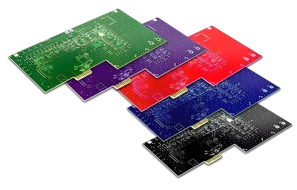
4.Flame Retardancy and Environmental Compliance
FR4 used in high-voltage circuits must meet UL94 V-0 flame-retardant requirements, which are mandatory in most industry standards. As environmental regulations become increasingly stringent, halogen-free flame-retardant FR4 has become the mainstream choice. Halogen-free FR4 uses phosphorus–nitrogen synergistic flame-retardant systems and does not release toxic brominated gases during combustion, ensuring compliance with RoHS and REACH standards. However, the addition of halogen-free flame retardants may slightly affect dielectric properties, making it essential to select formulations optimized to balance flame retardancy and insulation performance.
Common Misconceptions in High-Voltage FR4 Selection
Misconception 1: Focusing Only on Dielectric Strength While Ignoring CTI
Dielectric strength reflects bulk insulation performance, while CTI reflects surface insulation performance. Some engineers assume that high dielectric strength alone is sufficient and overlook the risk of surface tracking. For example, an industrial high-voltage power supply used FR4 with dielectric strength of 30 kV/mm but CTI of only 300 V. After three months of operation, surface tracking caused by dust accumulation led to short-circuit failure. Proper selection requires simultaneous consideration of both dielectric strength and CTI.
Misconception 2: Blindly Pursuing High Tg Values and Wasting Cost
Higher Tg provides better thermal stability but also increases material cost. In some low-voltage, high-temperature applications, engineers unnecessarily select FR4 with Tg ≥ 200 °C, increasing costs by more than 30%. If the operating temperature is only 100 °C, FR4 with Tg ≥ 170 °C is fully sufficient. Tg selection should be based on actual thermal requirements rather than excessive parameter margins.
Misconception 3: Ignoring the Impact of Thickness on Voltage Withstand Capability
Dielectric strength represents voltage withstand capability per unit thickness, meaning overall voltage withstand is proportional to substrate thickness. Some engineers pursue ultra-thin PCBs for compactness and select FR4 with a thickness of 0.1 mm. Even with dielectric strength of 30 kV/mm, the total withstand voltage is only 3 kV, insufficient for a 5 kV application. Thickness must be calculated in conjunction with operating voltage to ensure adequate overall insulation performance.
Misconception 4: Confusing Flame-Retardant Grades and Overlooking Halogen-Free Requirements
While UL94 V-0 is the baseline flame-retardant requirement for high-voltage circuits, some engineers overlook environmental compliance and select brominated FR4 materials. Although brominated FR4 can achieve V-0 ratings, it releases toxic gases during combustion and does not meet environmental requirements for applications such as new energy vehicles and medical equipment. Material selection must therefore account for both flame-retardant grade and environmental regulations, favoring halogen-free FR4 where required.
Selecting FR4 for high-voltage circuits is never about choosing the highest possible parameters, but about achieving the best match between material properties and application requirements. Under the stringent conditions imposed by high electric fields, FR4’s insulation performance, tracking resistance, and thermal stability together form the circuit’s safety barrier. Looking ahead, as high-voltage circuits evolve toward higher voltages, smaller form factors, and greater environmental sustainability, FR4 technologies will continue to advance, providing increasingly robust support for the safe operation of high-voltage electronic systems.