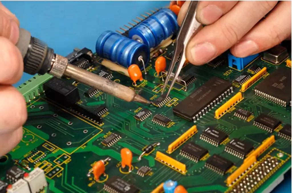
Circuit boards carry various electronic components and are connected through complex wiring to realize the function of the device. However, with the growth of the use of time, the circuit board will inevitably fail, which will require circuit board repair. IC board repair is not only a technical work, but also an art, requiring repairers to have rich experience and exquisite skills.
IC board repair skills
- Familiarize yourself with the circuit board schematic
Familiarize yourself with the schematic diagram of the circuit board is one of the keys to repair. Only by understanding the schematic diagram of the circuit board, you can understand the interrelationship between the components and the role, so as to better troubleshooting. - Pay attention to the details of the components
When repairing the circuit board, you need to pay attention to the details of the components, such as the component model, specifications, location and so on. These details may directly affect the normal operation of the circuit board. - Reasonable use of tools
When repairing circuit boards, you need to use a variety of tools for testing and debugging. Therefore, the rational use of tools is also one of the keys to repair. For example, when using an oscilloscope, you need to choose the right probe and set parameters for better detection of signal waveforms.
Common methods of circuit board repair
- Observation method
The observation method is one of the most basic repair methods, which finds potential failure points by observing the appearance and operation of the circuit board. This method requires experienced repairers who are able to determine the possible causes of failure based on the observed phenomena. - Replacement method
Replacement method is a commonly used repair method, which detects faults by replacing suspicious components or chips. This method requires the maintenance personnel to have enough spare components or chips so that they can replace them in time when the fault is found. - Debugging method
Debugging method is a way to troubleshoot by adjusting the parameters of the circuit board. This method requires maintenance personnel to have sufficient technical level and debugging experience, through debugging to find out the potential failure points. - Comparison method
Comparison method is a way to identify faults by comparing the parameters of normal circuit boards and faulty printed circuit boards. This method requires maintenance personnel to have two sets of the same type of pcb board, in order to compare and analyze.
IC board repair steps
Step 1
First of all, we get the circuit board should not be immediately desoldered or energized, but should first be visually inspected. Carefully review each component on the circuit board to see if there are obvious signs of burning, blowing, discoloration. At the same time, pay attention to see if there are components or circuit board copper foil corrosion or fracture. Based on the IC silkscreen information on the board, we can understand the year the board was manufactured, which helps us predict certain possible failures. For example, older circuit boards may be more prone to electrolytic capacitor failure, so we should focus on this part.
Step 2
It is crucial to get an in-depth understanding of the user’s feedback on board failures. Understand the specific phenomena when the failure occurs, such as the inability to power on, no display or a specific alarm code, etc. The more detailed this information is, the more it will help us to accurately determine the cause of the failure.
Step 3
Use a multimeter to test the on/off condition of each component on the circuit board to ensure that the components that should be on are unobstructed, and those that should not be on should remain disconnected. For example, fuses and coils must be guaranteed to pass through; if testing reveals that the fuse is not passable, this is often a clear point of failure. It is also important to keep an eye on the pins of components such as capacitors, diodes, and transistors to make sure that they do not have abnormal access.
Step 4
After the above steps, we can try to power up the board. The normal operation of the power supply is a prerequisite for the normal operation of the circuit board. We should pay special attention to the power conversion parts of the circuit board, such as the three-terminal voltage regulator chip, transformer, energy storage inductor, DCDC module, etc., to ensure that their output voltage is normal.
Step 5
If the power supply is normal, we should next determine the direction of finding fault characteristics according to the specific fault description provided by the user. For example, if the fault alarm is overvoltage, we should focus on checking the voltage detection part of the circuit; if the alarm is overcurrent, we need to distinguish between true overcurrent or false overcurrent, and accordingly look for the corresponding drive circuit or current sampling detection circuit. We should try to find the exact damaged components.
Step 6
If conditions allow, we can use the comparison method to locate the fault point. For example, if there are identical circuit boards or circuit parts available for comparison, we can compare their working conditions to quickly locate the fault location.
IC board repair is a job that requires both skill and art. It requires repairers to be experienced and skillful, as well as to remain patient and attentive.
