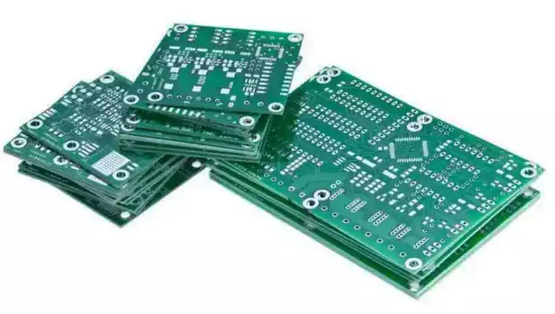
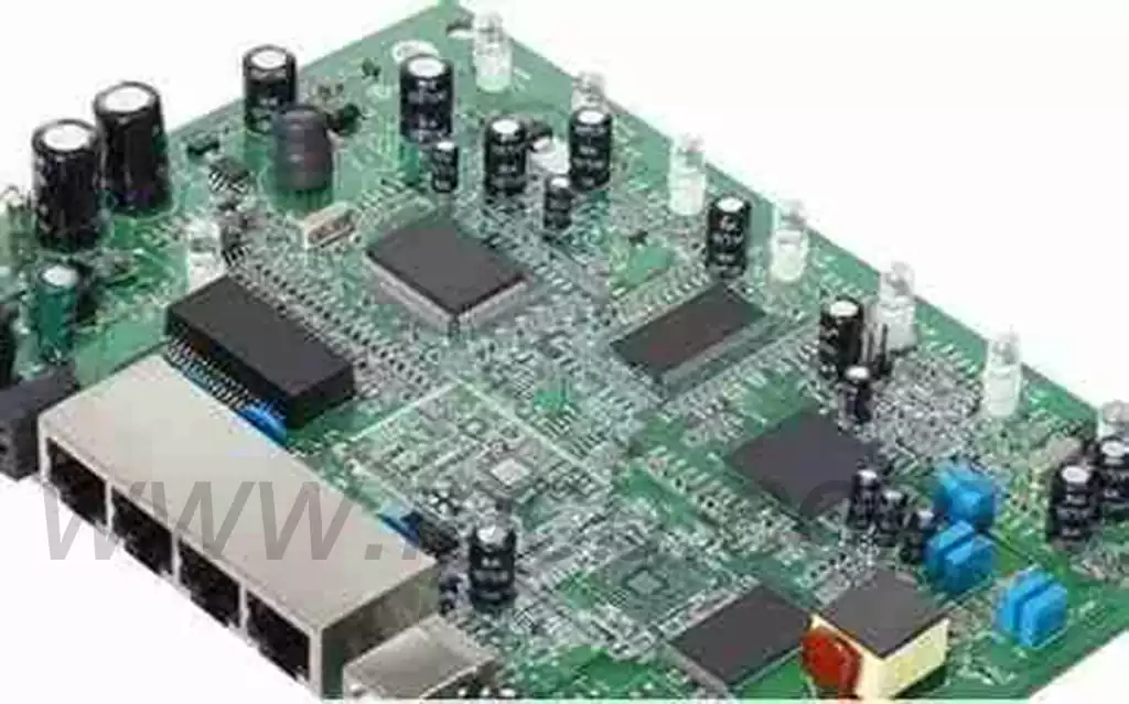
The IPC-A-600G standard, entitled Acceptability of Printed Circuit Boards, stands as the most comprehensive and visually detailed guide to PCB quality assessment within the electronics industry. Meticulously developed by the Association for the Electronics Industry (IPC), it serves as an indispensable reference for manufacturers, inspectors, and engineers throughout PCB production and procurement processes.
As the authoritative benchmark for PCB acceptance, IPC-A-600G employs photographs and illustrations to provide exceptionally detailed visual criteria. These standards meticulously depict the target, acceptable, and non-acceptable states for externally observable and internally observable characteristics of bare boards. This standard aligns closely with acceptance requirements specified in the IPC-6012D and IPC-6013C performance specifications, robustly ensuring compliance with current industry expectations.
IPC-A-600G categorises PCBs into three distinct performance grades based on their intended use, reliability requirements, and service life:
IPC-A-600 defines PCBs into three classes, each with distinct acceptability criteria tailored to end-use applications. Understanding these classifications is crucial for selecting the appropriate quality level for a project.
Category 1: General Electronics
Category 1 PCBs are designed for applications prioritising basic functionality over extended reliability. Typical examples include consumer electronics such as toys, low-cost gadgets, or household appliances. Acceptability standards for Category 1 are relatively lenient, permitting minor defects like slight solder bridging or small surface scratches provided they do not compromise functionality.
Key Specifications: Minimum ring circle diameter of 0.009 inches (0.23 mm), relaxed conductor spacing tolerances, and acceptance of minor cosmetic imperfections.
Applications: LED lighting, budget smartphones, or simple remote controls.
Category 2: Dedicated Service Electronics
Category 2 PCBs suit products requiring extended lifespan and reliability, though not demanding uninterrupted operation. These boards are prevalent in industrial control systems, telecommunications equipment, and automotive applications. Compared to Class 1, this standard imposes stricter tolerances on characteristics such as plating thickness and conductor width.
Key specifications: Minimum ring length of 0.006 inches (0.15 mm), enhanced solder mask coverage requirements, and reduced tolerance for voids or cracks.
Application scenarios: Network routers, automotive dashboards, or industrial sensors.
Category 3: High-Performance Electronics
Category 3 PCBs are engineered for mission-critical applications demanding uncompromising sustained performance and reliability, such as aerospace, medical devices, and military systems. These boards undergo the most rigorous inspection with minimal tolerance for defects like plating voids or dielectric issues.
Key Standards: Minimum ring size of 0.002 inches (0.05 millimetres), precise conductor spacing (e.g., 0.1 millimetres for high-density interconnects), and zero tolerance for functional defects.
Applications: Pacemakers, satellite systems, or avionics control units.
Key Acceptance Criteria in IPC-A-600G
IPC-A-600G establishes explicit acceptance criteria for numerous PCB characteristics, categorised into externally observable features and internally observable features:
Externally Observable Features
These characteristics or defects can be directly observed and assessed from the circuit board’s external surface:
Board edge condition: Covering burrs, gaps, and halos.
Substrate surface: Including exposed weave texture, weave lines, pitting/cracking, and voids.
Subsurface characteristics: Such as white spots, microcracks, delamination/blistering, and foreign inclusions.
Solder paste and molten solder coating: Exhibiting wetting and de-wetting phenomena.
Through-hole plating defects: Nodules/burrs, pink rings, copper plating voids, and final coating voids.
Marking defects: Issues with clarity and accuracy.
Printed contacts S: Surface plating and edge burr problems.
Solder mask defects: Manifesting as undercoverage and adhesion issues.
Internal observable characteristics
Accurate assessment of these features requires micrographic examination or other specimen preparation methods:
Dielectric materials: Issues include laminate voids, registration deviations, and delamination/blistering.
Metal-clad through-holes: Concerns relate to internal positioning, annular positioning, and foil crack positioning.
Drilling defects: Problems include pinheads and burrs.
Key Acceptance Criteria Differences Across Performance Grades
Significant variations exist in acceptance standards across the three performance grades, with key distinctions including:
Copper Plating Voids in Plated Through-Holes
Grade 3: No voids permitted within any hole.
Grade 2: One void permitted per hole, with voids affecting ≤5% of total holes and void length ≤5% of hole length.
Grade 1: Requirements more lenient than Grade 2.
Delamination/Bubbling
Class 2 and 3: Affected area ≤1% per side; conductor spacing must not fall below minimum values; distance spanning adjacent conductors must not exceed 25%.
Class 1: Similar area requirements, but slightly more lenient for spanning adjacent conductors.
White Spots
All grades: Acceptable unless specifically noted for high-voltage applications.
The Importance of IPC-A-600G in PCB Manufacturing and Quality Control
Implementing the IPC-A-600G standard delivers numerous significant advantages for PCB manufacturing and procurement processes:
Standardised Quality Assessment: IPC-A-600G establishes a unified acceptance standard that transcends organisational boundaries, achieving consistency in quality assessment across the global electronics industry. This standardisation helps eliminate subjective interpretations of PCB quality, ensuring all stakeholders share common expectations and evaluation methods.
Enhanced Visual Reference: The standard incorporates over 120 new or revised photographs and illustrations, providing comprehensive visual guidance to assist inspectors in accurately identifying and classifying various conditions and defects. This visual reference material is particularly crucial for training newly recruited quality control personnel and resolving disputes between manufacturers and customers.
Support for Automated Inspection: The standard provides a useful foundation for understanding and interpreting Automated Inspection Technology (AIT) results, facilitating the transition towards more automated quality control processes while maintaining alignment with industry standards.
Process Improvement Technical Reference: By clearly defining acceptable and non-conforming conditions, IPC-A-600G assists manufacturers in identifying specific process defects and implementing targeted improvements, thereby enhancing yield and product reliability.

How can enterprises apply IPC standards?
Define product grades: Select appropriate grades based on application scenarios—e.g., automotive boards require Grade 2 or above—avoiding cost escalation from excessive grade pursuit.
Production benchmarking control: Translate standards into process parameters—e.g., controlling etching burrs to ≤0.03mm per IPC-A-600 Grade 2 requirements.
Unify quality inspection standards: Train inspectors to assess defects according to IPC definitions, eliminating subjective bias.
Establish communication benchmarks: Clearly define adopted IPC levels and standard numbers with clients to minimise acceptance disputes.
Tips for Effective IPC-A-600 Implementation in PCB Projects
Select Appropriate Class Early: Determine PCB class during design to meet application requirements. For instance, Class 3 boards for satellite systems demand tighter tolerances (e.g., 0.05mm conductor spacing) than Class 1 boards for toys.
Invest in training: Participate in IPC-A-600 certification programmes, such as Certified IPC Specialist (CIS), equipping inspectors with skills to identify defects like cracking or plating voids.
Employ automated inspection tools: Automated Optical Inspection (AOI) systems can measure conductor widths with 0.01mm precision, ensuring compliance with IPC-A-600 standards.
Collaboration with manufacturers: Work closely with PCB suppliers to establish acceptance criteria, particularly custom requirements like impedance control (e.g., 50 ohms ±10% for RF circuits).
Documented inspection: Maintain detailed records of inspection results, including defect types and measurement outcomes, to trace issues back to the manufacturing process.
In today’s burgeoning electronics industry, PCBs serve as the core components of electronic devices, where quality and reliability are paramount. The IPC-A-600G standard, with its comprehensiveness, authority, and practicality, provides a robust foundation for PCB quality assessment. For PCB enterprises, a thorough understanding and correct application of this standard not only ensures stringent control over product quality but is also key to enhancing competitiveness and earning customer trust. Looking ahead, as emerging technologies and applications continue to proliferate, the PCB industry will face heightened challenges and demands. The IPC-A-600G standard will evolve accordingly, persistently providing precise quality benchmarks for the sector. This will empower enterprises to continually drive innovation, propelling the entire electronics industry towards higher levels of development.


