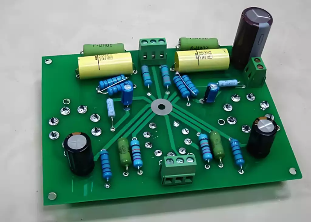
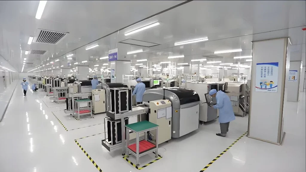
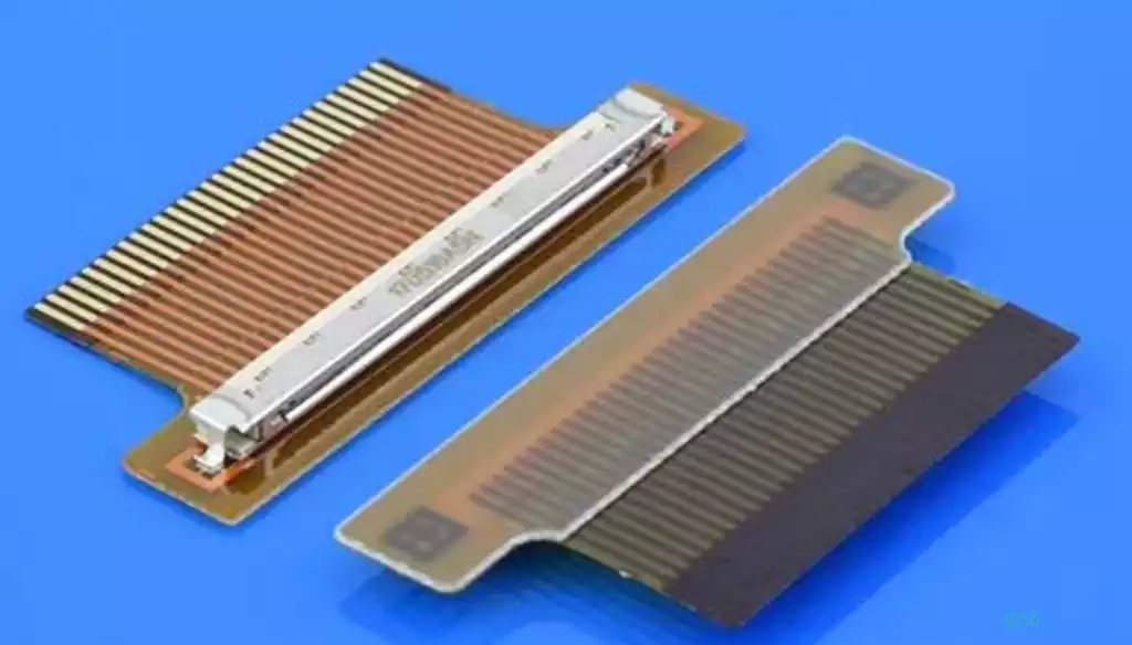
Microphone PCB is a key component of audio equipment, mainly used to support the microphone’s electronic components and circuit connections. A microphone is a device that converts sound signals into electrical signals, and microphone circuit boards can be divided into two main types: dynamic and condenser.
Moving Coil Microphone PCB
A moving coil microphone vibrates the diaphragm inside the microphone with sound waves. The voice coil attached to the diaphragm moves in the magnetic field, cutting the magnetic lines of force and generating an induced current, which converts the sound waves into electrical signals. The electrical signal is then amplified and processed through the PCB by connecting it to other electronic components. The PCBs of these microphones are generally simple in design and are suitable for use in noisy environments as their principle of operation requires high sound pressure levels. The PCB is usually equipped with robust circuitry to ensure signal strength and clarity.
Condenser Microphone PCB
The condenser microphone pcb is responsible for connecting and supporting the various electronic components and circuits inside the condenser microphone. This type of microphone is widely used in professional recording, broadcasting, music production and audio equipment due to its high sensitivity and excellent sound quality. Condenser microphones work through changes in the electric field, using changes in capacitance triggered by the vibration of the film to generate an electrical signal.
Microphone PCB design principles
Signal path optimisation
Optimising the signal path is an important principle in the design of microphone PCBs. The signal transmission path should be as simple and direct as possible to reduce signal attenuation and delay. This specifically includes:
Ensure that signal lines are as short as possible to minimise signal loss.
Avoid sharp turns and redundant coupling, which helps to improve signal quality.
Ensuring that signal lines are properly spaced to avoid crosstalk.
Good Grounding Layout
A good grounding design can effectively reduce noise and interference and improve signal quality. Design considerations include:
Use a star grounding layout to ensure that all grounding points are brought to a common ground.
Use a large grounding area to reduce contact resistance and improve EMC.
Ensure that there is a good connection between the signal lines and ground to avoid the formation of ground loops.
Power Management
A stable power supply is the basis for proper microphone operation. The design needs to pay attention to the following aspects:
Noise filtering: Add decoupling capacitors to the power input to eliminate high frequency noise.
For low-power components, use a voltage regulator to ensure that the power supply voltage is stable and to avoid unnecessary voltage fluctuations.
Keep power lines separated from signal lines to reduce the impact of power supply noise on the signal.
Reasonable Layout of Components
The layout of components directly affects the integrity of signal transmission and the performance of the circuit. Design recommendations to follow include:
Place sensitive components (e.g. amplifiers, filters) as close as possible to the signal source to minimise interference and transmission losses.
Ensure that high-frequency components are separated from low-frequency components to avoid unwanted signal interference.
Reasonable placement of components on the PCB to ensure good heat dissipation.
Material Selection
Choosing the right PCB material is critical to the performance of the microphone. Commonly used materials such as FR-4 can balance cost and performance. Factors to consider include
The dielectric constant of the material: a reasonable choice of material can reduce signal attenuation and improve signal transmission.
Select materials with high temperature resistance and low expansion to enhance the long-term stability of the device.
Improve anti-interference ability
The design of microphones needs to consider the influence of external electromagnetic interference (EMI). The following measures can be taken:
Add a shielding layer to the PCB to isolate the effect of external EMI on the signal.
Use differential signal transmission to reduce sensitivity to common mode noise.
Reduce crosstalk by routing sensitive audio signal lines away from power and high-speed signal lines.
Testing and Verification
Once the design is complete, adequate testing and verification is a critical step in ensuring the performance of the microphone PCB:
Carry out comprehensive functional tests to ensure that all functions work correctly.
Analyse the signal quality using oscilloscopes and spectrum analysis instruments to check for noise or distortion.
Verify the supply voltage and its stability to ensure that the system operates reliably under different operating conditions.

Considerations for choosing microphone PCB materials
When designing a microphone printed circuit board, choosing the right material is critical as it directly affects the performance, signal quality and long-term stability of the circuit. When choosing a material, a number of factors need to be considered to ensure optimum performance of the final product. The following are the key factors to consider when selecting materials for microphone PCB:
Dielectric Constant
The dielectric constant is an important indicator of the electrical properties of a material as it behaves in an electric field.Choosing a material with a low dielectric constant reduces signal delay and transmission loss, ensuring the quality of high frequency signal transmission.Therefore, when designing microphone PCBs, choosing materials with lower dielectric constants can improve audio signal integrity and reduce distortion.
Mechanical strength
The materials used for microphone PCB needs to have good mechanical strength to withstand the handling during production and the physical impact of the final product in use. Materials with insufficient mechanical strength may cause the PCB to deform at high temperatures or under other environmental conditions, leading to circuit failure. Therefore, the strength and toughness of the material directly affects the reliability of the PCB.
Temperature resistance
Microphone PCB may be exposed to high temperatures during operation, so it is very important to select materials that are resistant to high temperatures. The material should be able to withstand changes in the operating temperature range without changes in physical or chemical properties. For example, high TG (Transition Temperature of Glass) materials are suitable for use in high temperature environments and can ensure stable operation of the PCB under high loads.
Flame Retardant
Since risks such as high temperatures and short circuits may be involved in electronic devices, it is important to select materials with flame retardant properties. This improves product safety and prevents equipment damage caused by fire. When selecting materials for microphone PCB, checking the flame retardancy rating is one of the bases for ensuring product quality.
Adaptability to the production process
The production process of the material should also be considered. Some materials may be easier to process in the manufacturing process,effectively reducing the difficulty and time of production. For example, FR-4 material is widely used in microphone PCB design due to its good processability and moderate cost. Understanding the processing characteristics of your chosen material can help to achieve a more efficient production process.
Frequency response characteristics
The frequency response characteristics of different materials have a direct impact on the accuracy of signal transmission.For some high-frequency applications, choosing a low-loss, high-frequency material (such as ceramic-filled PCB materials) can effectively improve transmission and ensure the accuracy and clarity of audio playback.
The design of microphone PCB needs to consider signal path, grounding, power management, component layout and material selection to ensure sound quality and stability.Through fine design and proper material selection, the overall performance of the microphone can be improved to meet the actual application requirements. Therefore, these key elements should be continuously focused on and optimised during the design and production process.


