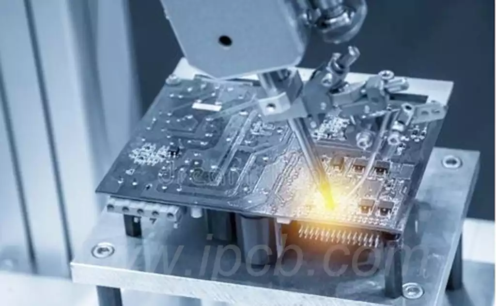
In the PCB prototyping process, PCB rework is the process of repairing or modifying a PCB that has already been produced. When a sample PCB has design errors, soldering problems, component failures, or other non-conformities, the rework process can help fix these problems so that the PCB meets the design requirements and works properly.
Steps in PCB rework:
Inspection and Diagnostics: First, the PCB in question is carefully inspected to determine the problem. This can include visual inspections, measurements, and tests to identify specific failure points or problems in the PCB.
Solder Repair: If the problem involves a soldered connection, a re-solder repair may be required. This may include re-soldering with a soldering iron or re-melting the solder joints with a heat gun to ensure a good solder.
Component Replacement: Failed components will need to be removed from the PCB and replaced with new components. This can be done with a heat gun or other appropriate tool.
Circuit Modification: In the event of a design error or circuit connection problem, circuit modifications may need to be made to the PCB. This can include adding or removing components such as resistors, capacitors, inductors, etc., or correcting circuit paths through jumper cable connections.
Cleaning and inspection: After the rework is complete, the repaired PCB board is cleaned and inspected to ensure that all issues have been resolved and no new problems have been introduced.
6 Ways to Rework a PCB
Make the PCB bigger
Prototypes rarely need to be as small as the final design, so make the prototype PCB larger and place it into an off-the-shelf prototype enclosure. This will allow you to release your design faster and waste less time dealing with tricky PCB layout issues. To test as part of a system, use cables to connect the larger prototype PCB to tight locations in the system. Larger PCBs are easier to work with on the bench, easier to probe, and easier to rework.
Using Larger Components
While it may seem cool and edgy to use miniature BGA components or 01005-package resistors, you probably don’t need them and you certainly don’t need them on your prototype. You can’t easily rework parts smaller than a grain of sugar. For prototypes, consider using parts no smaller than 0402 unless absolutely necessary, and use parts with exposed leads rather than BGA or QFN packages whenever possible.
In the μModule Product Guide, LinearTech reminds us how ugly rework can be. (This is what happens when you don’t design for rework)
Allow more clearance
Rework is easier and more reliable when there is more clearance around the part. For BGAs, QFNs, or other packages without exposed leads, allowing enough space around them is critical for localized rework reflow heating. For high-density connectors or press-fit connectors, clearance is required for tooling that utilizes the PCB. For mechanical parts such as heat sink snap-in pins, clearance for hand tools such as pliers is important.
Layout Bundle Resistors and Jumper Options
The goal of the circuit designer is to design everything correctly the first time. However, you can save a lot of time and hassle by designing strapping resistors to pull all setup pins high or low with simple rework. Or consider adding additional no-fill filter circuitry around the power regulator. You can even design an entire secondary circuit by simply moving jumpers from one connector to another.
Using Programmable Parts
When possible, use programmable parts for rework flexibility. Adjusting firmware is often easier than cutting traces or re-soldering components. Look for where a programmable voltage regulator, microcontroller, or CPLD/FPGA might make sense in a prototype, even if it is not the intent of your final design. Simple, inexpensive programmable parts allow you to redesign your design without putting the hardware at risk.
Install all programming headers
Not following this guideline has failed many designers. Spending a few extra cents to install every pesky programming header file. I can hear you all saying, “It’s me who can program that part through the JTAG chain, or maybe we built that part with the same code for a long time and we don’t have a chance to change it.”
Rework is an inevitable part of the PCB design and prototyping process. In the face of design errors, soldering problems, component failures and other challenges, the rework process is not only a repair of the problematic PCB, but also an optimization of the design and an increase in efficiency.