PCB inductors in the circuit is usually divided into two parts: a part of the circuit graphic symbols, indicating the type of inductor; part of the letters + numbers, indicating that the inductor in the circuit of the serial number and the main parameters. Circuit graphic symbols can reflect the basic types of inductors, the lead from the circuit graphic symbols extend from both ends, and circuit diagrams in the circuit line connected to the text marking often provides the name of the inductor, the serial number and inductance, model number and other parameter information.
Inductance is a property of a closed loop, i.e., when the current through the closed loop changes, an electric potential occurs to resist the change in current. This inductance is called self-inductance and is a property of the closed loop itself.Assuming that a change in current in one closed loop produces an electromotive force in the other closed loop due to inductive action, this inductance is called mutual inductance.When two inductive coils are close to each other, the change in the magnetic field of one inductive coil will affect the other inductive coil,and this effect is mutual inductance.The size of the mutual inductance depends on the self-inductance of the inductive coil and the degree of coupling of the two inductive coils,the use of this principle made of components called mutual inductors.
Inductors are characterized as follows:
Inductors have a high Q value and less attenuation of signals,making them suitable for low-loss applications.
Inductors have a high self-resonant frequency and perform well in high frequency applications.
Inductors are relatively inexpensive and easy to procure.
A PCB inductor is a passive electronic component capable of storing energy from a magnetic field.Its operating principle is based on Faraday’s Law of Electromagnetic Induction,which states that a current passing through a coil produces a magnetic field,and an electric potential is induced in the coil when the magnetic field changes.The main functions of inductors include:
- Filtering and energy storage:
In power supply circuits,pcb inductors are commonly used in LC filter circuits, which can eliminate AC ripple and stabilize DC voltage; meanwhile, in switching power supplies, inductors can also store and release energy and play a role in smoothing the output. - Resonance:
PCB inductors and capacitors can form a resonant circuit,used for signal frequency selection,frequency tuning and other occasions. - Impedance Matching:
The use of pcb inductors in the transmission line for impedance conversion, to ensure that the signal source and load to achieve the best energy transfer efficiency. - EMI Suppression:
While pcb inductors can also stop the propagation of high-frequency noise to some extent, they are usually less targeted than magnetic beads.
Inductive circuits are circuits based on inductive components and are of the following types:
- Inductive series circuit
An inductive series circuit is a circuit consisting of multiple inductive elements connected together.In a series circuit,the total inductance of the pcb inductors is equal to the sum of the inductance of each inductor,whereas the current in the series circuit is the same and the voltage is distributed across each inductor in proportion to the inductance of the inductor. - Inductive parallel circuit
An inductive parallel circuit is a circuit in which the ports of several inductive elements are connected in parallel. In a parallel circuit, the total inductance of the inductors is equal to the sum of the reciprocal of the inductance of each inductor, and the voltage in the parallel circuit is the same, and the current is distributed to each inductor inversely proportional to the inductance of the inductor. - LC Circuit
The LC circuit is a resonant circuit consisting of an inductive element and a capacitive element, which is frequency selective and can be used in circuits such as filters and oscillators. In an LC circuit, when the capacitor voltage and current change sinusoidally with time, and the phase difference between the capacitor voltage and current is 90 degrees, the circuit is in resonance, and the response of the circuit is the most sensitive. - Mutual inductance circuit
Mutual inductive circuit is composed of two or more inductive components coupled to each other and the circuit. In the mutual inductive circuit, the change of current will cause the change of magnetic field in the mutual inductive element, so as to produce an induced electromotive force in another mutual inductive element, to realize the transmission and conversion of energy. Mutual inductor circuits are widely used in power transmission and conversion, wireless communication and other fields.
Chip inductor is an electronic component also known as chip inductor or surface mount inductor It is commonly used on circuit boards to store and filter electrical energy, reduce electromagnetic interference (EMI),and stabilize current.Compared with traditional plug-in inductors, chip inductors offer smaller size, lighter weight, and higher reliability,and are therefore widely used in modern electronic devices.
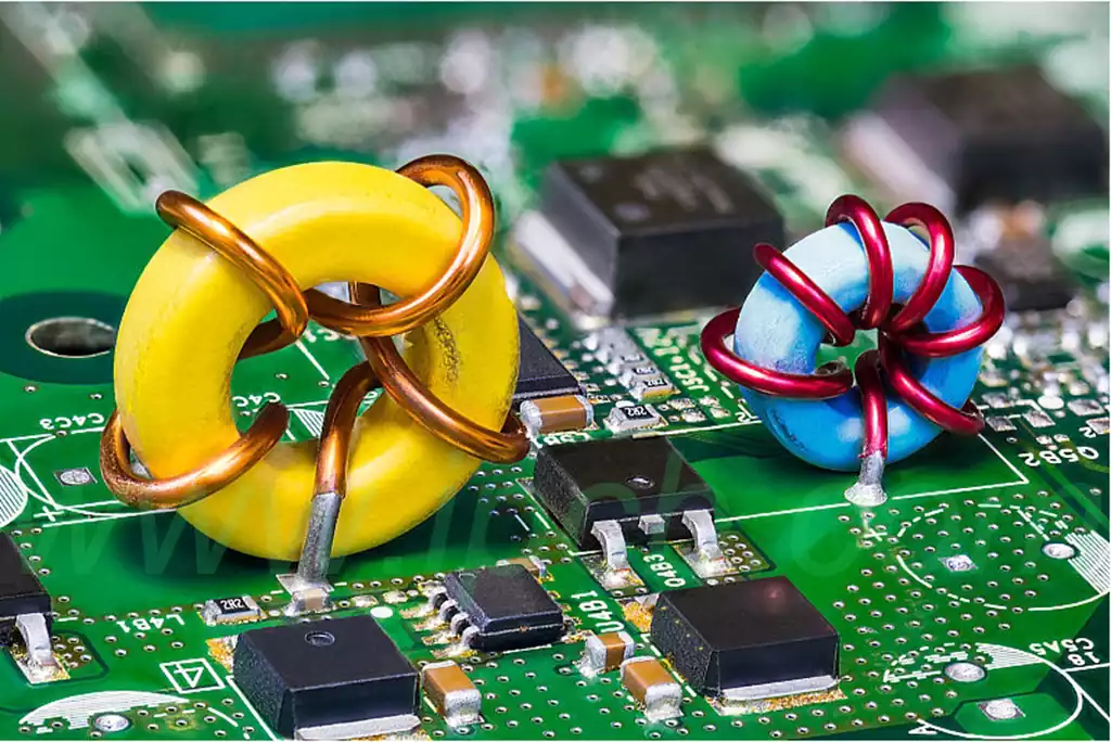
The composition of pcb inductors is mainly composed of two parts, the winding and the core, which include:
It consists of a coil of conductor wound on a magnetic core, usually made of copper or aluminum wire, with the cross-sectional area of the wire and the number of turns determining the size of the inductance. The windings can be single or multi-layer windings, or parallel or cross wire windings.
Core: It can be made of various materials such as hollow tube type, solid magnetic material or magnetic powder, etc. The material of the core affects the performance of the pcb inductor,which is involved in transmitting the magnetic field, and its main function is to increase the magnetic flux of the inductor parts.
It is worth noting that the internal structure of the inductor will be different because of the specific application scenarios and different manufacturing processes, such as the core of the iron core inductor is composed of iron, nickel, iron oxide and other materials, as well as various types of miniature inductors, SMD inductors and so on, the structure of which are also different.
In addition, there are some inductor parts will be attached to the anti-shaking capacitors, winding protection sleeve and other auxiliary components, in order to improve circuit efficiency and protect the structure of the inductor.
In PCB design, there are due to the inductor work in the magnetic field will be generated, the magnetic field will change with the change of time. If this magnetic field is strong enough,it will interfere with the surrounding electronic equipment.This interference can lead to problems such as degradation of circuit performance and signal interference.
In order to minimize inductor interference with surrounding electronic equipment, it is common to gouge out some of the copper skin around the pcb inductor. This is because the magnetic field generated by the inductor is conducted to the surrounding electronic equipment through the copper skin. If we dig out the copper skin, we can reduce the radiation range of the magnetic field, thus reducing the impact of EMI.
In addition to digging out the copper skin, other measures can be used to reduce the inductor’s interference with the surrounding electronic equipment. For example, they can place a shield around the inductor to further reduce the radiation range of the magnetic field.In addition,low-noise power supplies, ground lines and other techniques can be used to reduce the impact of EMI.
In conclusion, EMI is a very important issue in PCB design. An inductor is a common electronic component that generates a magnetic field, and this magnetic field may interfere with the surrounding electronic equipment. In order to minimize this interference, it is common to gouge out some copper around the inductor and use other measures to reduce the impact of EMI. These measures can help us design a more stable and reliable circuit system.
As an indispensable component in the circuit, the PCB inductors not only carries important functions such as filtering, energy storage, resonance and impedance matching, but its unique magnetic field characteristics also make it an important consideration in electromagnetic interference (EMI) management. Reasonable PCB layout design can effectively reduce the magnetic field generated by the inductor on the surrounding electronic equipment interference, to ensure the stable operation of the circuit system.