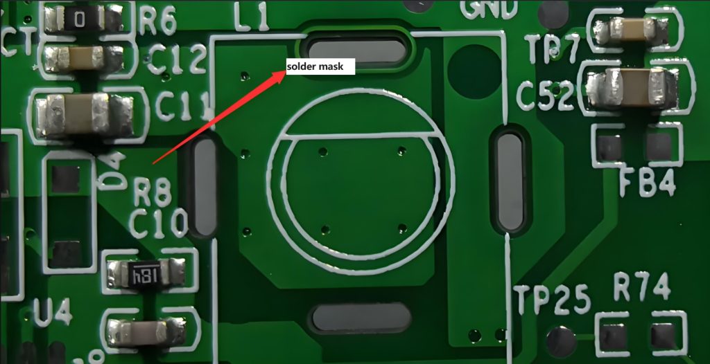
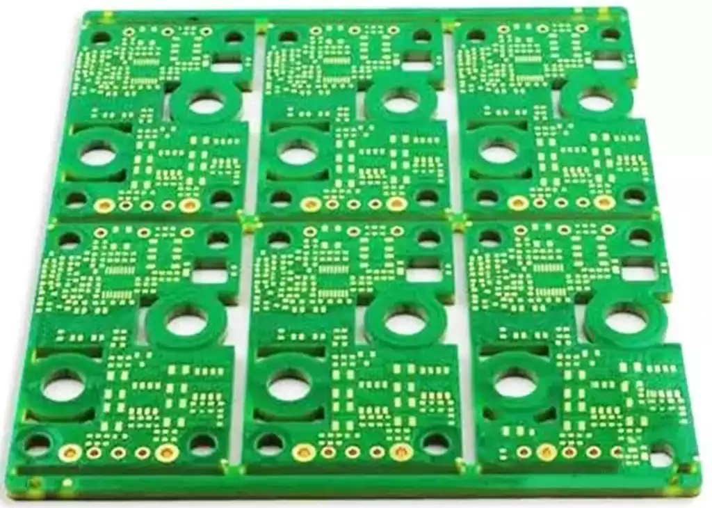
The pcb mounting holes are used to position or support the PCB for mounting. These holes are generally large and cover the external wiring, and can lead to incorrect mounting if not placed correctly.
Basic Tips for Designing PCB Mounting Holes
In PCB design, the setting of mounting holes is an important part. EDA365 Electronics Forum summarizes here some basic tips for designing the holes to help you better complete the design.
First, be sure to pay attention to the coordinate position of the mounting holes. Wrong coordinates will directly lead to the PCB can not be correctly installed into the shell, so it must be accurate.
Second, make sure the size of the mounting holes matches the selected screws. Mounting holes that are too large or too small may result in poor mounting or failure to secure the screws.
In addition, when choosing the location of the mounting holes, avoid placing them too far from the edge of the PCB. Less dielectric material at the edge may cause cracks in the PCB during installation or removal, affecting the service life.
At the same time, sufficient clearance should be left between the mounting holes and other components to avoid mutual interference and collision.
Finally, with the help of advanced circuit design software, such as Altium Designer, it is easy to place mounting holes and define relevant safety spacing rules, thus improving design efficiency and accuracy.
How to use PCB holes to minimize EMI?
Connecting mounting holes to signal ground may result in direct EMI intrusion into the signal loop, damaging the integrity of the signal. This is because signal ground is usually directly connected to sensitive components in the circuit, and any interference may adversely affect these components. Therefore, we cannot simply connect the mounting holes to the signal ground to avoid introducing unwanted interference.
Instead, connecting the mounting hole to the enclosure chassis ground is a much more logical choice. The chassis ground serves as the point of convergence for all ground connections, effectively collecting and directing electromagnetic interference from within the equipment to earth. By connecting the mounting holes to the chassis ground, we can ensure that any EMI entering the device through the mounting holes is effectively shielded and eliminated.
PCB holes are not only used to securely fasten circuit boards to the enclosure beyond their physical mechanical function, but they also have an application in terms of electromagnetic function – to reduce electromagnetic interference (EMI).
For EMI-sensitive PCBs, they are usually placed inside a metal enclosure. To effectively minimize EMI, the PCB’s mounting holes need to be plated and connected to ground. By ground shielding in this way, any EMI generated can be directed from the metal enclosure to ground, thus eliminating the interference.
Novice designers often ask the question: to which ground should the mounting holes be connected? In electronic equipment, there is usually a signal ground, an enclosure base ground, and a ground ground. According to the experience of EDA365 Electronics Forum, it is not recommended to connect the mounting hole to signal ground. Signal ground is the reference ground for electronic components in a circuit design, and it is not wise to introduce electromagnetic interference into it.
In fact, it is the enclosure chassis ground that should be connected. This is the point where all ground connections for the entire chassis come together and should be connected in a star pattern. This avoids ground loops and multiple ground connections, which can lead to voltage differences that can cause current to flow between chassis grounds. Finally, chassis ground should be connected to earth for safety protection.
In the design and manufacturing process of electronic equipment, we need to pay full attention to the design and application of PCB mounting holes. Through reasonable design and precise manufacturing, we can ensure the stability and reliability of the circuit board and improve the performance of the whole equipment.