Prototype pcb assembly refers to the assembly of electronic components, wires, connectors and other parts on a circuit board according to the circuit design diagram to form a circuit board sample with a specific function. This process is important for verifying the circuit design, optimizing product performance, and shortening the development cycle.
Basic flow of PCB prototype assembly
Component Procurement and Preparation
Before PCB assembly, electronic components need to be procured and prepared. The selection of electronic components should be based on the requirements of the circuit design, and the quality and reliability of the components also need to be considered. Components need to be inspected after procurement to ensure that their quality meets the requirements.
PCB Board Preparation
Preparation of the PCB board is required prior to PCB assembly. This includes cleaning and inspecting the surface of the PCB to ensure that it is free from issues such as dirt, oxides and damage. The size and location of the PCB board also needs to be checked to ensure that components can be mounted and soldered correctly.
Component Mounting
Prior to component mounting, the layout and positioning needs to be done according to the circuit schematic. The components are then mounted onto the PCB board, either manually or through automation. When mounting components, attention also needs to be paid to the orientation and position of the components to ensure that they are mounted correctly.
Soldering
After mounting the components, soldering needs to be performed. Soldering can be done manually or by automation. Manual soldering requires the use of a soldering pen or gun to solder the components to the PCB. Automated soldering usually uses surface mount technology to solder the components to the PCB.
Testing
After soldering is complete, testing is required to ensure the performance and reliability of the board. This can be done using automated testing or manual testing. Automated testing usually uses test instruments such as multi-purpose testers or network analyzers. Manual testing usually requires the use of test tools such as multimeters or oscilloscopes.
Packaging and Shipping
After testing the boards, they need to be packaged and shipped. Different packaging methods can be used, such as anti-static bags, foam boxes or cardboard boxes. In addition, a final inspection is required before packaging and shipping to ensure that there are no problems with the circuit boards.
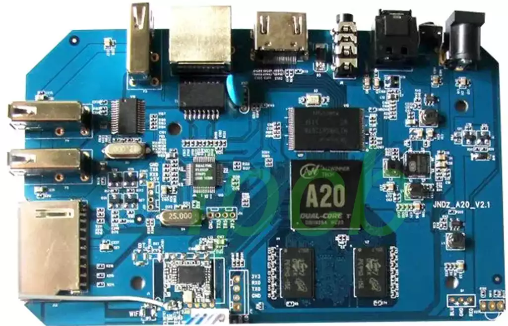
Types of PCBA
PCBAs can be categorized based on a variety of factors, such as the assembly technology used, the complexity of the circuitry, and the intended application.The main types of PCBAs include through-hole assembled PCBAs, surface mount assembled PCBAs, and mixed technology PCBAs.
Through-hole assembly PCBAs use through-hole components whose leads are inserted into holes drilled in the PCB and soldered on the other side. This assembly technique has been widely used for decades and is known for its robust mechanical connections and ease of prototyping. However, through-hole components are typically larger and require more space on the PCB, making them less suitable for high-density and miniaturized designs. Through-hole assembled PCBAs are commonly found in older electronics, power electronics, and applications that require strong mechanical connections.
Surface mount assembly PCBAs utilize SMT, where components with pads are placed directly on the PCB and soldered to the traces using a reflow soldering process.SMT components are smaller and can be mounted on either side of the PCB, resulting in higher component densities and more compact designs. Surface mount assembly PCBAs are widely used in modern electronics such as smartphones, computers and IoT devices for their improved performance characteristics and space-saving benefits.
Mixed-technology PCBAs combine through-hole and surface-mount components on the same board, taking advantage of the benefits of each assembly technology. This approach is often used when a specific component is only available in one form factor, or when design requirements need to combine the mechanical robustness of through-hole connections with the high-density capabilities of surface mount technology. Mixed-technology PCBAs are used in a variety of applications, including industrial controls, automotive electronics and medical devices.
In addition to this, there are several other types of assemblies, such as flexible PCBAs and Ball Grid Array (BGA) PCBAs. flexible PCBAs are designed to be bent and curved, making them ideal for applications where space is limited or where the PCB needs to conform to a specific shape. BGA PCBAs, on the other hand, utilize integrated circuit surface mount packaging technology and offer a compact footprint, high lead count, and enhanced thermal and electrical performance. These specialized PCB types are often used in devices that require complex designs and high flexibility, such as aerospace, medical devices, and high-performance computing applications.
The choice of which type of PCBA to use depends on factors such as design requirements, available components, desired performance characteristics, and project budget. By understanding the differences between these types of PCBAs, engineers and designers can make informed decisions that best meet the needs of their specific applications.
Prototype PCB assembly is a key link in the design and production process of electronic products, which is not only a bridge connecting the designer and the final product, but also an important step in verifying the circuit design, optimizing the product performance and shortening the development cycle. With the continuous development of electronic technology, this assembly technology is also in constant innovation and progress.
