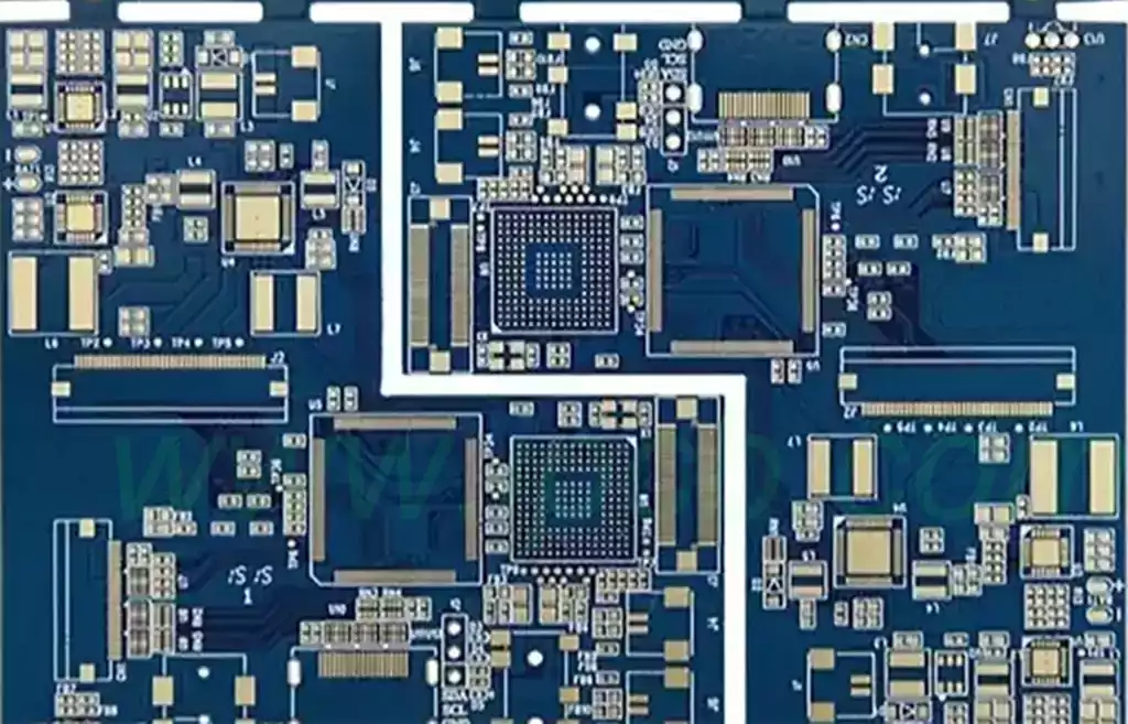
Radar PCB is an important component of the radar system, responsible for signal transmission, data processing, and the transmission and reception of radio waves. It is a printed circuit board specifically designed for radar systems, which integrates various electronic components and circuits to achieve signal transmission, processing, and conversion functions. Compared with ordinary PCB boards, Radar PCB has higher performance requirements, requiring features such as high-speed signal processing, low noise, and high stability. Due to the high precision requirements for radar signal acquisition, details such as through holes and microstrip lines are very high.
Radar PCB uses FR-4 PCB, ceramic PCB, Teflon PCB, PTFE PCB, Buried copper block PCB, Rogers PCB etc. The FR-4 PCB is mainly a double-sided or multi-layer circuit board, responsible for data transmission and processing of the radar system. The high-frequency circuit board is responsible for the transmission and reception of radio waves in the radar system.
The basic components of a radar PCB include
Transmitter: The signal from the waveform generator is not strong enough for the radar. Therefore, the purpose of the transmitter is to amplify the signal using a power amplifier.
Receiver: The receiver uses a receiver processor (such as superheterodyne) to detect and process reflected signals.
Antenna: includes parabolic reflectors, planar arrays, or electronically controlled phased arrays. It is responsible for sending and receiving pulses.
Duplexer: A duplexer is a device that enables an antenna to complete transmitter and receiver tasks.
Radar PCB is widely used in various radar systems, such as automotive collision radar, millimeter wave radar, weather radar, military radar, phased array radar, etc.
The automotive radar PCB plays a crucial role in the safety performance of modern cars, helping drivers to timely grasp the surrounding environmental information of the vehicle and improve driving safety. Therefore, choosing high-quality automotive radar circuit boards in the market is crucial.
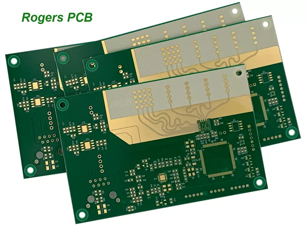
This car radar circuit board uses Rogers RO3003G2+FR-4 high-frequency hybrid board, suitable for car millimeter wave radar. In automotive millimeter wave radar, the PCB substrate is responsible for signal transmission, reception, and processing, achieving accurate measurement of distance and speed between vehicles.
Due to the fact that any change in the dielectric constant of circuit boards will have an impact on the performance of millimeter wave automotive radar systems, another important parameter to consider for the board is the effect of temperature on the dielectric constant Dk. This parameter refers to the change in dielectric constant over the entire test temperature range in a short period of time. Because typical commercial vehicles face the challenge of a wide operating temperature range, the stable operation of automotive radar systems at 77GHz and 79GHz is a crucial parameter. Some laminates exhibit a temperature time constant error Dk exceeding+200 ppm/° C at a given temperature and frequency. The RO3003 PCB board, designed specifically for high-frequency antennas and circuits, has a temperature time constant error Dk better than+11ppm/° C in the temperature range of 10GHz frequency -50 ° C to+150 ° C.
In weather radar, they are responsible for signal processing and display, helping meteorologists analyze weather conditions and predict weather changes. Weather radar PCB is a special type of radar PCB specifically designed for weather radar systems. Compared to conventional methods, it needs to meet higher performance and stability requirements in order to operate normally under various adverse weather conditions.
The working principle of meteorological radar is to emit electromagnetic energy pulses into the atmosphere at microwave frequencies. When these pulses encounter an object, some electromagnetic energy will scatter back to the radar. This is commonly referred to as reflection back, which is the origin of the term reflectivity. Reflectivity is an indicator that measures the energy efficiency of radar target interception and return, depending on the physical parameters of the target, such as size, shape, direction, and composition.
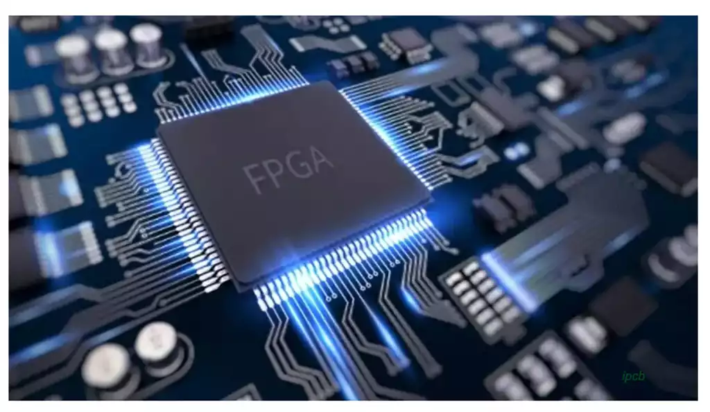
Phased array radar(PAR) does not have a single rotating antenna, but guides electromagnetic pulses through many small antenna arrays. Most of them also have dual polarization ability.The phased array radar technology requires high-end electromechanical equipment that combines ultra large scale integrated circuits, all solid-state transceiver units, high-speed computers, and high-speed communication technology.It requires interdisciplinary and multi professional R&D personnel and technology to integrate and cooperate with each other.
Phased array radar requires mature PCB processing technology and COTS system design.
In military radar, it also plays an important role, responsible for target detection, tracking and recognition functions. Military radar is a military electronic equipment that uses electromagnetic waves to detect targets. The electromagnetic waves emitted by the radar illuminate the target and receive its echo, thereby discovering the target and determining its position, direction of motion, velocity, and other characteristics.
The requirements for radar PCBs are very high, and electronic manufacturers need to have strong PCB technology and years of manufacturing experience to ensure the production of high-quality radar PCBs. At the same time, mature PCB design software, high-quality materials, and precision processing equipment are required to meet the high-performance requirements of radar PCBs. Factors affecting radar circuits:
PCB design: PCB design is crucial for the performance of radar. Special attention should be paid to issues such as waveguide and RF impedance matching during the design process. Electronic manufacturers need to use high-performance PCB design software, such as Altium Designer, Mentor Graphics, etc. At the same time, it is necessary to pay attention to factors such as PCB thickness, number of layers, and board area to ensure the stability and performance of the circuit.
PCB material: The materials used for radar PCBs need to meet the following conditions: good high-frequency performance, good thermal stability, high mechanical strength, good corrosion resistance, etc. Therefore, electronic manufacturers need to choose high-quality materials such as PTFE, high-performance fiberglass, etc. to ensure the high performance and long lifespan of PCBs.
Manufacturing process: In the manufacturing process of radar PCB, special attention should be paid to special processes, such as copper foil thickness control, microstrip line width control, flying needle through holes, etc. Electronic manufacturers need to use high-precision processing equipment in the manufacturing process, such as laser punching machines, lithography machines, etc., to ensure the high precision and quality of PCB manufacturing.
The working frequency band of the radar will continue to expand towards both ends of the electromagnetic spectrum. The application of microelectronics and solid-state technology will achieve miniaturization of radar. By utilizing computers to manage and control radar, automation of operation, calibration, performance, and fault detection will be achieved, and adaptive anti-interference technology will be developed. In small and medium-sized ground, shipborne, and airborne radars, phased array technology will be widely applied to achieve radar multifunctionality; It will enhance the radar’s ability to recognize the actual image, size, movement posture, and decoy of targets, and enhance its ability to resist nuclear attacks and anti radiation missile destruction. And new radar systems will be developed, such as multi base radar, passive radar, spread spectrum radar, noise radar, etc.
As an important component of radar systems, radar PCBs face certain challenges in design and manufacturing due to their high cost and production difficulty. The manufacturing of these Radar PCBs by iPCB requires advanced processes and technologies, including high-precision circuit design and wiring technology, high-quality insulation and conductive materials, and fine drilling and welding techniques. Meanwhile, the manufacturing process of Radar PCB requires strict quality control and inspection to ensure that the quality of each link meets the requirements.