SMD Resistor (SMD Resistor), also known as Chip Fixed Resistor (Chip Fixed Resistor), is a type of metal glaze resistor. It is a resistor made by mixing metal powder and vitreous enamel powder and printed on a substrate using the screen printing method [1]. It is resistant to humidity and high temperature, and has a small temperature coefficient. It can greatly save the cost of circuit space and make the design more refined.
Chip Resistor Resistance Value and Tolerance Labeling Methods
1.Resistor Tolerance and Code
The tolerance of general chip resistor has 4 levels: B, D, F, J. The tolerance is earth 1%o, earth 5%o, earth 1% and ±5% respectively. The tolerance is 1%o, 5%o, 1%o and ±5% respectively, of which B, D, F are precision resistors and J are ordinary resistors.
- Resistance range and nominal resistance value
Different precision grade, different size of the resistance value range (different factories are not the same) Generally 1Ω ~ 10MΩ, low resistance type for 10 ~ 910mΩ, ±5% precision of each resistance value according to the E24 standard sub-block, the earth 1%o, 5%o, 1% precision of each resistance value according to the standard sub-block of E48, E96, see table.
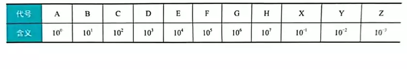
For example, by the chip resistor standard resistance value table can be seen, 08C for 118 × 100 = 11.8kΩ, 19E for 154 × 10000 = 1.54MΩ.
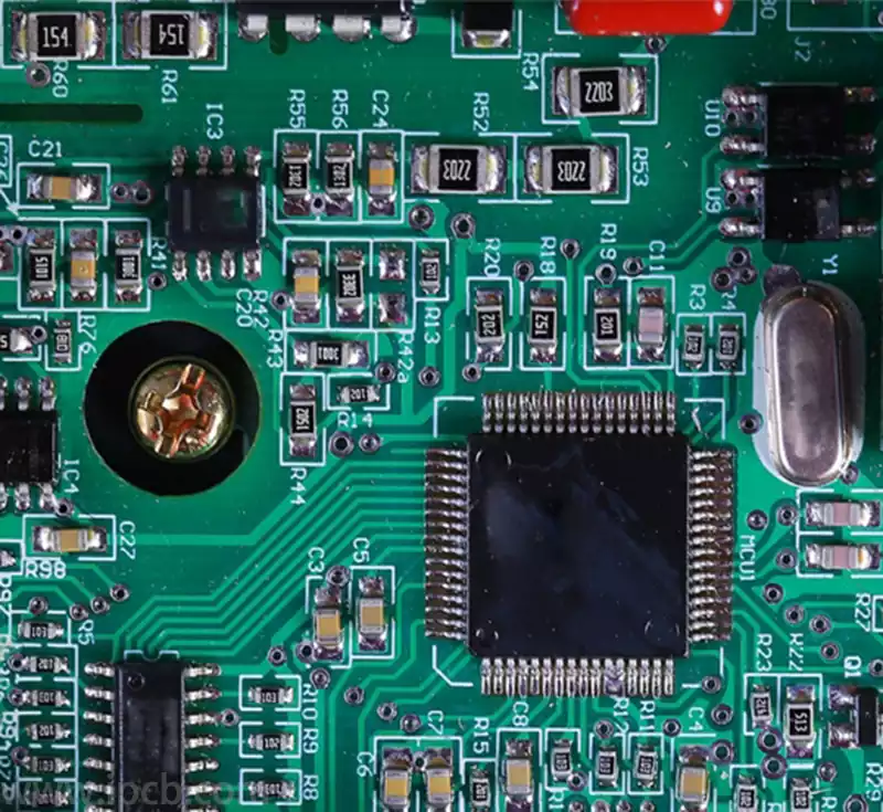
Some of the chip resistors are expressed by IEC (International Electrotechnical Commission) code. Resistance value is generally directly labeled in the resistor which side, white letters on a black background, usually expressed in three digits, the first two digits indicate the effective value, the third digit indicates the effective number of digits after the number of zeros, when the resistance value is less than 10 Ω, to × R × said that the R is regarded as a decimal point. For example, R33 means 0.33Ω, 3R3 means 3.3Ω, 33R means 33Ω and so on.
Production process
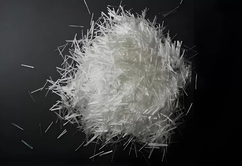
- Raw material and substrate preparation
At the beginning of production, we first select suitable ceramic materials (such as alumina) as the substrate, and ensure its flatness and thickness consistency through fine processing. - Back conductor printing
A layer of paste containing a metal component (e.g. Nichrome) is coated on one side of the ceramic substrate using screen printing technology to form the back electrode, followed by high temperature sintering to solidify the metal layer and make it tightly bonded to the substrate. - Forward Conductor Printing
The printing and sintering process is repeated on the other side of the substrate, but this time the front electrode is printed at the specified location, which will serve as the point of contact between the resistor body and the external circuit. - Resistive Layer Deposition
Using a high-precision printing process, a specially formulated resistive paste is applied to the front side electrode. This step determines the basic resistance value of the resistor. - Resistor Sintering
The substrate with the resistive paste is sintered again at high temperature, so that the resistive paste is converted into a stable resistive film, thus realizing the predetermined resistance value. - Insulation Layer Processing
In order to isolate the potential between the resistor and the conductor, a layer of vitreous enamel or other insulating material is usually printed and sintered again to ensure good insulation properties. - Laser Resistance Tuning
Through laser fine-tuning technology, the resistor film is precisely trimmed to achieve the required accuracy of resistance value. - Marker printing and sintering
According to the need, using screen printing on the resistor body to print a digital code or logo, representing its resistance value, series number and other information, followed by sintering fixed. - Cutting and Packaging
After completing the above steps, the entire resistor is initially and secondarily cut to form the final product size, and the ends are encapsulated, for example, using silver paste or sputtered metal layers to enhance the solderability of the terminals. - End Hardening
The encapsulated ends are hardened to improve the mechanical strength and heat resistance of the terminals. - Electroplating Electrodes
Carry out necessary plating process on the end to enhance the conductivity and oxidation resistance of the terminal. - Quality Inspection and Testing
Finally, each chip resistor is subjected to strict electrical performance tests, including resistance measurement, temperature coefficient test, voltage withstand test, etc., to ensure that the product meets the design specifications and quality standards. - Packaging and Shipping
The inspected and qualified ic chip resistors will be packaged in tape and reel or pallet according to the standard quantity for the automated mounter to pick up and ultimately deliver to the customer. In summary, the production process of SMD resistors is a series of complex physicochemical processes, whereby each step is precisely controlled to achieve high efficiency, mass production and high consistency of the resistive components.
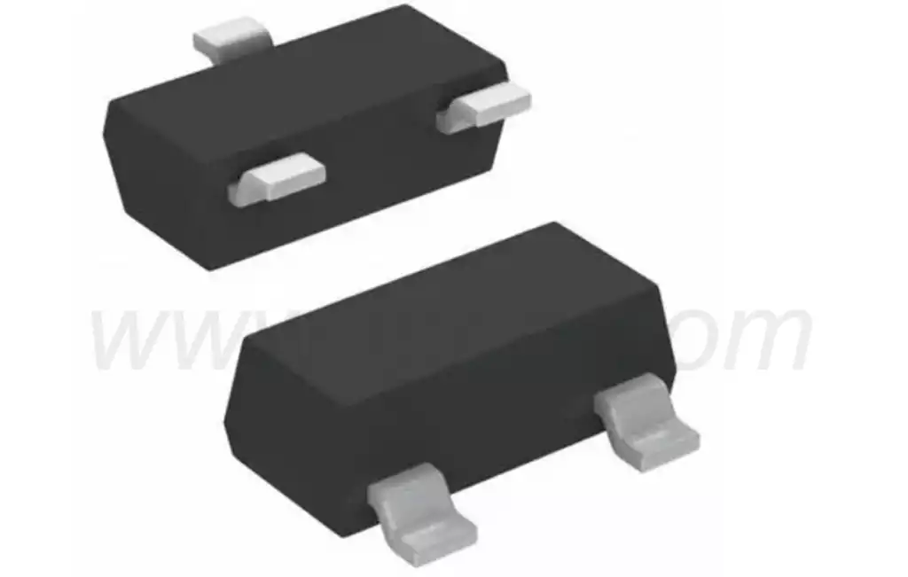
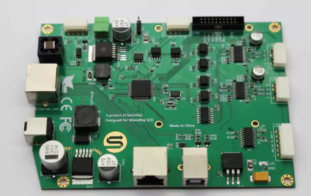
SMT resistors or SMD resistors are rectangular in shape, which is why they are often referred to as chip resistors.
They have metallized areas at each end of the main ceramic body so that they can be set on a printed circuit board that has pads on which the ends are set to provide connections.
SMD resistors are made from resistive material which is deposited on a porcelain or ceramic substrate. The external terminals of the resistor are connected to the substrate for easy soldering and connection, and have the following characteristics:
Small size and light weight
Easy to automate assembly
Suitable for high density circuit boards
High reliability and stability
Various resistor values and accuracy available
Applications:
SMD resistors are widely used in electronic devices including:
Smart phones, tablets and laptops
Communication devices
Medical devices
Industrial control systems
Automotive electronics
Aerospace
Chip resistors, small but strong, with exquisite craftsmanship and a wide range of applications, become an important cornerstone of electronic technology, helping various types of equipment towards a smarter, more efficient future.