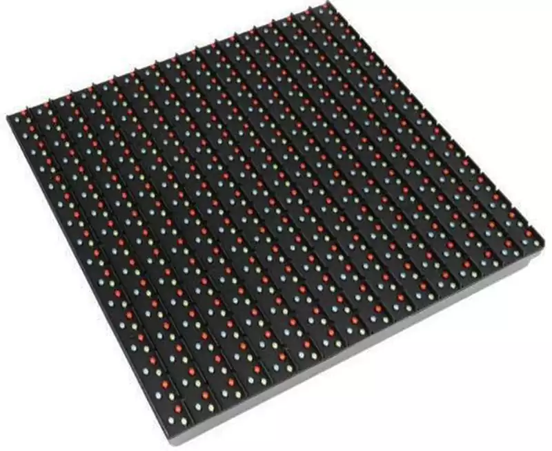
Black PCB LED strip refers to LED strip lighting products utilising printed circuit boards (PCBs) with black solder mask as their substrate. LED chips and associated electronic components are mounted onto this PCB surface via surface mount technology (SMT).
Simply put, it is an LED strip featuring a black circuit board. While structurally and functionally identical to standard LED strips, it offers distinctive aesthetic appeal and application effects.
Core components of black PCB LED strip:
1.Black Flexible Printed Circuit Board (Flexible PCB)
This serves as the strip’s ‘skeleton’ and ‘nervous system’.
Base Material: Typically employs flexible materials such as polyimide (PI), enabling the strip to bend.
Black Solder Mask: A layer of black ink (solder resist) applied over the copper foil. This black coating not only imparts a sleek aesthetic but also protects the circuitry from oxidation and short circuits.
Rolled Copper: Internal wiring employs highly conductive copper foil to transmit electrical current.
2.LED Light-Emitting Chips
The core of the strip, converting electrical energy into light.
Package Types: Common variants include SMD 5050 (larger size, high brightness), SMD 2835 (high efficiency), or COB (continuous light emission, no light spots).
Colour Classification:
Monochrome: Emits only a single light colour such as white, red, or blue.
RGB/ARGB: Integrates red, green, and blue chips internally, producing millions of colours through mixing.
3.Control Components (Resistors & ICs)
To prevent diodes from being damaged by excessive current, the PCB is populated with minute electronic components.
Current-limiting resistors: Regulate the current flowing through the diodes to prevent burnout from overcurrent.
Control IC (Smart/Addressable Strips Only): In ARGB (addressable) strips, each LED or group is accompanied by a micro-IC (e.g., WS2812B). This chip receives data commands to execute dynamic effects like running lights or rainbow transitions.
4.Surface Finish & Protective Coating
Surface treatments vary based on application environments:
Bare PCB (IP20): No coating applied, offering optimal heat dissipation. Suitable for installation within aluminium channels.
Drip-coated (IP65): Surface covered with a layer of transparent silicone or epoxy resin, providing dust and water resistance.
Fully tubed (IP67): Entire black PCB encased within a silicone tube, suitable for outdoor or humid environments.
5.Adhesive Backing & Connectors
3M Adhesive: Most strips feature high-tack 3M adhesive tape on the reverse for direct mounting to enclosures or walls.
Connectors: Common interfaces include 4-Pin (RGB) or 3-Pin (ARGB). Black PCB LED strip typically incorporate black wiring for visual consistency.
Four Core Principles in Black PCB LED Strip Design:
1.Thermal Management Priority
Black solder mask ink absorbs heat more readily than white and lacks the white PCB’s ability to reflect heat towards light outlets, making black strips more prone to heat accumulation.
Increase Copper Foil Thickness:
Recommendation: Use 2oz or higher rolled copper. Thicker copper foil not only reduces resistance but also functions as a longitudinal heat spreader, rapidly conducting heat generated by the LEDs across the entire PCB.
Optimise Copper Pour Area:
Where circuit insulation remains unaffected, maximise the copper pour area on the negative or ground plane to create extensive heat dissipation pads.
Metal Core Substrate Selection: For high-power strips (e.g., 5630 or high-density COB), prioritise aluminium core printed circuit boards (MCPCBs) over traditional FR-4 or single-layer flexible PI. This leverages metal’s high thermal conductivity for rapid heat dissipation.
2.Voltage Drop Mitigation Principles
Extended installations are common for LED strips, where black PCBs are typically employed for applications demanding optimal visual aesthetics. In such scenarios, brightness inconsistencies become markedly apparent.
Wider Traces: The visual concealment of black PCBs permits designers to appropriately widen the main power trace width (recommended 1.0mm or greater) to reduce trace resistance.
Double-sided routing design: Employ double-sided PCB layout, placing LEDs and control ICs on the front surface while routing high-current power lines on the reverse side, interconnected via vias. This not only minimises voltage drop but also increases heat dissipation surface area.
Zonal power supply planning: For strips exceeding 5 metres in length, incorporate multiple power injection points during design to prevent colour deviation in end LEDs due to voltage drop (e.g., reddening at the ends of RGB strips).
3.Optical Compensation Principle
Black PCBs absorb approximately 10%-20% of stray light, resulting in lower light output (lumens) compared to white PCBs of equivalent specifications.
Selecting High-Efficiency LEDs: To counteract light absorption by the black substrate, employ LED chips with higher lumen efficacy (such as high-efficiency 2835 or 5050 chips).
Luminance Calibration: When designing firmware or controller parameters for ARGB (addressable) strips, appropriately increase brightness coefficients or enhance physical LED density (e.g., 144 LEDs/metre) to ensure visual brightness meets specifications.
White Silk Screen Masking: Although the substrate is black, a minimal area of white ink or bare tinned copper may be retained around LED pads to enhance light extraction efficiency through micro-reflection.
4.Manufacturing Reliability Principles
Black PCBs impose higher demands on soldering processes than green or white substrates.
Solder Pad Opening Design: Black solder resist ink is thicker and opaque, making it difficult to observe wetting during soldering. Design must ensure precise solder mask openings to prevent pad coverage by solder resist, which causes cold solder joints.
Clear Silk Screen Contrast: On black backgrounds, high-contrast white or pale yellow silk screen printing must clearly indicate polarity (+ / -), data direction (DI/DO), and cut lines to prevent installation errors leading to component burnout.
Solder mask adhesion: Matte black ink typically facilitates better heat dissipation than gloss black and resists fingerprint marks. However, its chemical compatibility must be verified during design to prevent delamination during potting waterproofing processes.
Black PCB LED strip represents not merely a colour variant but a specialised solution offering enhanced aesthetic appeal, luminous efficiency, and engineered design. From material selection and thermal management to voltage regulation and manufacturing processes, every detail directly impacts their stability and visual output. Only through a thorough understanding of black PCB characteristics and adherence to scientific design principles can the unique value of black PCB LED strip be fully realised in high-end lighting, gaming environments, and professional decorative applications.