PCB circuit board is an indispensable component of modern electronic equipment. It is based on strong fiberglass and coated with one or more thin layers of copper foil to connect and support electronic components.
Part 1: Basic knowledge of PCB circuit boards
Before we dive into the design aspects of PCB circuit boards, let’s first understand some basics. A PCB circuit board is a thin sheet covered with conductive material that is used to connect and support electronic components. It connects electronic components to each other through contact points and lines to enable the normal operation of electronic equipment. PCB circuit board design is based on specific circuit functions and layout requirements.

Part 2: Interpreting PCB circuit boards
When we get a PCB circuit board, we can take the following steps to read it and interpret its functions.
The first step is to observe the appearance and size of the entire PCB circuit board. By observing its length, width and shape, we can initially judge its use and applicable scenarios. For example, larger sized circuit boards are often used to develop complex electronic devices, while smaller sized circuit boards are common in portable devices.
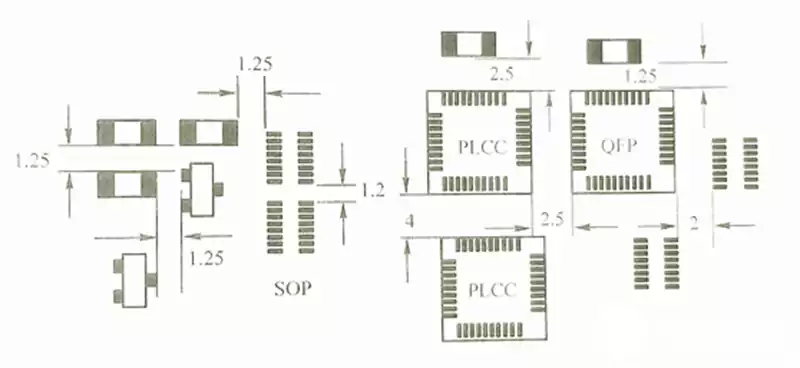
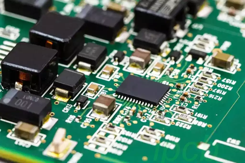
The second step is to take a closer look at the traces and components on the circuit board. The circuits on the circuit board are usually displayed in precise geometric shapes, such as rectangles, circles, straight lines, etc. The shape, width, and layout of the traces all reflect the design and functionality of the circuit board. There is usually filler material between the lines to isolate and protect the circuit. In addition, we can also see components such as pads and pins, which are used to connect and secure various components.
The third step is to understand the components on the circuit board. Components can be capacitors, inductors, transistors, relays, etc. Each component plays a different role in the circuit, such as storing electrical energy, amplifying signals, or switching circuits. We can identify components by their logos, colors and sizes, and learn more about their functions and specifications through circuit drawings or device models.
Look for the mark on each component. These markings often include part numbers, numerical values, or manufacturer identification. These markings can provide important information about component specifications.
The fourth step is to analyze the connection methods and wiring rules on the circuit board. By carefully observing the direction and connection of the lines, we can determine the signal transmission path and the structure of the circuit. Wiring rules stipulate the spacing, width and direction of lines, etc. These rules will affect the performance and stability of the circuit.
Trace the connections along the wires (copper wires) on the PCB to understand how the components are connected to each other. Wires carry electronic signals. If necessary, use a magnifying glass to trace small wires. PCB boards can have multiple layers of wires. If the PCB is multi-layered, you may want to use the multimeter’s continuity mode to trace connections between components on different layers.
The fifth step is to read the circuit board markings: Circuit boards often have markings, labels, printed words, or icons that indicate components, connections, or other important information. Read these markings carefully, they may contain important information such as the component model, value, polarity, connection method, etc. This helps to better understand the functionality and design of the board.
The sixth step is Reference circuit diagrams and documentation: If possible, obtain a circuit diagram or related documentation for the circuit board. A circuit diagram is a graphical representation of an electrical circuit on a circuit board that can provide more detailed information. By comparing the circuit diagram with the actual circuit board, you can better understand the structure and function of the circuit board.
Through the above steps, we can gradually understand and interpret the PCB circuit board. When we can properly understand the composition and function of a circuit board, we can better troubleshoot, design modifications, and performance optimization. Mastering these skills not only helps us work better in the engineering field, but also develops our observation and analytical skills. Therefore, if you are interested in electronic devices and PCB circuit boards, I recommend in-depth study and practice to improve your skill level.
The above is all I shared, thank you for watching.


