The drilled hole tolerance of a pcb board is the tolerance between the diameter of the holes or slots drilled or milled during the PCB manufacturing process and the design requirements. This tolerance requirement is to ensure that the components on the board are installed correctly and can be well connected. Generally, the hole diameter tolerance requirement is clearly specified in the manufacturing drawings or design documents.
In the PCB manufacturing process, holes are usually formed using mechanical or laser drilling. Therefore, the aperture tolerance requirements are also related to the drilling process. For precision multilayer printed circuit boards, the aperture tolerance requirements may be more stringent to ensure a good connection between different layers. At the same time, it is also necessary to take into account the coating and surface treatment process of the hole wall to ensure that the hole size is not negatively affected during the manufacturing process.
PCB board drilling hole size tolerance requirements:
Generally the holes on the circuit board are divided into two kinds, one is with copper holes and no copper holes, with copper is mainly used for soldering and conduction holes, while no copper is mainly used for mounting and positioning use.
If the metallization drilling, we need to first drill copper-free holes in the PCB board, and then plating a layer of copper foil in the hole wall, then if the tin spray process needs to make up 0.1-0.15mm, that is, the drill needs to be used 0.2-0.25mm, the specific size of each factory according to the production process and machinery and equipment; if it is the OSP, chemical gold and other processes need to make up 0.05-0.1 mm or so.
If it is non-metallized holes, that is, no copper holes, then make up the value of about 0.05mm, such as 0.1mm holes need to use 0.15mm drill, of course, generally no copper holes are larger holes, according to the actual size of the compensation correction.
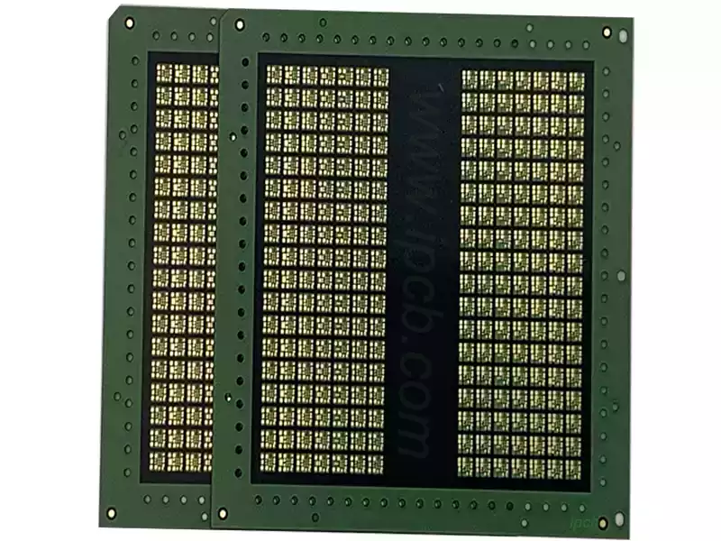
Customers generally do not have to take into account our compensation size in the design process, general manufacturers in the production process will default to the customer’s hole information for the finished hole size, circuit board manufacturers will do the information, automatically designed to compensate for the tolerance. Produce the hole size that the customer wants.
Drilling tolerance: PTH: min +/-0.075mm
NPTH: min+/-0.05mm
CNC tolerance: min+/-0.1mm
Aperture tolerance requirements are very important for the quality and performance of printed circuit boards. It can affect the reliability of soldering and the accuracy of component mounting on the board. If the aperture tolerance is too large, it can lead to poor solder joints or components can not be installed correctly, thus affecting the normal operation of the entire circuit. On the contrary, if the aperture tolerance is too small, it will lead to components can not be inserted or insertion and removal difficulties, and may even damage the components, thus increasing the maintenance cost.
PCB aperture size tolerance mainly affects the installation of plug-ins. Due to the high integration requirements of the circuit board, a variety of high-density plug-in components began to be applied to the single board, to the PCB aperture tolerance control has put forward more stringent requirements. PCB design should pay close attention to the ability of PCB manufacturers to control the aperture tolerance to avoid subsequent assembly problems.
Printed circuit board aperture drilled hole tolerance requirements is not only a key indicator in the PCB manufacturing process, but also a key factor in ensuring the overall quality and performance of the circuit board. It is directly related to the accurate installation of components and welding reliability, which in turn affects the stable operation of the entire circuit. Therefore, in the design and manufacturing process, must strictly control the aperture tolerance to ensure that it is within a reasonable range.
