Vehicle grade PCB sockets refer to printed circuit board end connectors that meet the requirements of harsh automotive environments such as high temperature, vibration, and humidity, and are used for signal/power connections of automotive electronic control units (ECUs) and other onboard devices. They have high reliability, high sealing (such as IP69K), miniaturized design, and solder free connections (such as ACTION PIN/Multispring), and are widely used in the field of automotive electronics.
Vehicle grade “refers to a product standard that means an electronic component or system that can undergo rigorous testing and certification to ensure stable, reliable, and safe operation in various extreme environments throughout the entire lifecycle of a vehicle.
Vehicle grade: Like a special forces soldier, it needs to complete critical tasks unconditionally and with zero errors in extreme environments such as extreme cold, extreme heat, high humidity, strong impact, and strong electromagnetic interference, with a service life of more than 10 years.
The core requirements of automotive grade standards can be summarized into the following aspects, and their authoritative standards usually point to the AEC-Q series (for components) and ISO/TS 16949 (for quality management systems, now evolved into IATF 16949).
Environmental reliability requirements
Cars can travel anywhere on Earth, and their electronic components must withstand:
Temperature: The working temperature range usually requires -40 ℃ to+85 ℃, or even higher (such as -40 ℃ to+125 ℃ near the engine compartment). Consumer grade chips typically only require 0 ℃ to 70 ℃.
Humidity: Must resist high humidity, condensation, and even waterproof and dustproof (IP rating).
Thermal shock: able to withstand huge temperature fluctuations in a very short time (such as a few minutes) (such as entering an underground garage to wash a car from the cold winter in the north).
Vibration and mechanical shock: Continuous vibration and instantaneous impact are caused by vehicle starting, driving, and collision. Vehicle grade components must undergo strict mechanical vibration and impact testing.
Chemical resistance: It needs to resist the corrosion of chemicals such as gasoline, engine oil, and cleaning agents.
Service life and durability requirements
Design lifespan: typically requiring 15 years or 200000 kilometers. This means that the component cannot experience functional failure throughout its entire lifecycle.
Long term stability: Material aging and performance degradation must be controlled at an extremely low level.
Quality and consistency requirements
High quality rate: The quality control during the production process is extremely strict
Batch consistency: The performance of products from different batches must be highly consistent without significant fluctuations.
Traceability: It is required to have a complete supply chain traceability system, which can quickly locate any problems that arise
Vehicle grade PCB sockets are mainly used for:
Connect the electronic control unit (ECU) of the car. The connection between the wiring harness and the PCB board. Vehicle control module, infotainment system, ADAS (Advanced Driver Assistance System), etc
Connect the electronic control unit (ECU) of the car
Connecting automotive electronic control units (ECUs) involves connecting various sensors (inputs), actuators (outputs), and other ECUs to a microcontroller through automotive buses (such as CAN, LIN) to process data and control vehicle functions
An automotive electronic control unit (ECU) is an embedded system in a vehicle that is responsible for managing and controlling various electronic features and functions. It ensures optimal performance by receiving input from sensors, processing data, and sending commands to different vehicle components. ECU is essentially the “brain” behind many systems, such as engine control, transmission, braking (ABS), airbags, infotainment, and advanced driver assistance systems (ADAS)
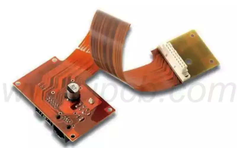
Connection between wiring harness and PCB board
The connection between the wiring harness and the PCB board is mainly achieved through two methods: connectors (sockets/pins/crimping terminals) and direct soldering,
The transition points between PCB routing and wiring harnesses can affect signal integrity, system level reliability, and manufacturability. Improper calibration of transition points can lead to impedance discontinuity, signal loss, or thermal stress. Mechanical strain and layout limitations can also limit wiring flexibility, complicate manufacturing, and potentially lead to long-term system failures.
For high current paths, please keep the wiring short and wide, and use copper plated copper and thermal vias for heat dissipation. The optimized wiring geometry reduces resistance, improves thermal performance, and ensures stable current transmission. Prioritize through-hole or surface mount connectors in challenging or dynamic environments, and avoid lap welding in high reliability applications. Safe and repeatable termination enhances durability and reduces the risk of mechanical or thermal cycling related failures.
Create and share clear assembly diagrams, pin diagrams, and color codes to reduce errors and facilitate maintenance. Accurate and accessible documentation ensures consistency in production and simplifies troubleshooting throughout the entire product lifecycle. Design Rule Check (DRC) enforces voltage, current, insulation, and wire gauge limitations, while the connector library supports correct terminal selection and pin mapping.
3D layout and MCAD integration can verify connector positioning, stress relief geometry, and mechanical clearances during assembly.
Thermal simulation models the heat dissipation of copper plated copper, routing copper, and thermal vias, which helps to adjust the layout to reduce local hotspots.
There are two types of sockets that we need to introduce. High frequency sockets (such as automotive USB-C and industrial Ethernet sockets) are often in a “wide temperature+frequent plugging and unplugging” environment – automotive scenarios need to withstand temperature fluctuations of -40 ℃~105 ℃, while industrial scenarios need to withstand more than 10000 plugging and unplugging cycles (10 times a day, usable for 3 years). If ordinary PCBs are not designed properly, they are prone to “solder joint detachment and substrate cracking”: a USB-C high-frequency socket PCB from a certain car company, due to the use of ordinary FR-4 (Tg ≈ 130 ℃), after 1000 cycles of -40 ℃~105 ℃, the substrate cracks, and the socket contact failure rate increases from 0.1% to 15%; The Ethernet socket in a certain factory had a poor PCB soldering process, and after 5000 insertions and removals, the soldering point fell off, resulting in an equipment disconnection rate of 8%. For high-frequency sockets, the “temperature resistance” and “mechanical strength” of PCB are the key to long-term reliability.
American car standard 1900W high-power AC socket
It is often installed in the rear seat of the intelligent driving cabin for the owner and passengers to use for power supply.
The product is compatible with American plugs and can provide AC power for devices that use American plugs in the car. Product applicable devices: laptops, drones, portable projectors, car refrigerators, electric kettles, etc.
Product Features
High environmental tolerance: capable of operating within an extremely wide temperature range (-20 ℃ to+115 ℃) and possessing vehicle grade seismic resistance (MIL-STD-810G).
High power support: Supports 1900W/20A output, suitable for American standard (NEMA) high-power devices.
Safe and reliable: It has high insulation and voltage resistance, and the material is made of flame-retardant PC+ABS.
Vehicle grade PCB sockets are crucial for vehicle reliability
With the enhancement of vehicle functions, risks also increase. Most serious faults in the automotive electronics field can be traced back to PCB level issues, such as thermal stress, electromagnetic interference, or design defects. In an industry where recalls can cost millions and safety and compliance are non-negotiable, poor PCB design is not a wise choice. With the development of automotive electronics technology, printed circuit boards have become increasingly complex, and their role in vehicles has shifted from being supportive to an essential function throughout the vehicle lifecycle. Poor quality PCB design increases the risk of performance issues, safety failures, and expensive recalls. Today we will discuss some viewpoints on the importance of correct PCB design for automotive electronics technology in terms of vehicle reliability