Virtual Welding is a common wiring fault, it refers to the solder joints at the solder joints are not completely effective welding together, resulting in poor contact, may appear on and off. Virtual soldering refers to the component pins, soldering ends, PCB pads at the tin is not sufficient, the wetting angle of the solder in this place is greater than 90 °, and only a small amount of solder to wet the pins, soldering ends, PCB pads, resulting in poor contact and sometimes on and off. Virtual soldering is generally oxidized or impurities in the soldering point and the soldering temperature is not good, improper method caused by the essence of the solder and the pins of the isolation layer exists between them. They are not completely in contact with each other. The naked eye generally can not be seen in its state. However, its electrical characteristics do not conduct or poor conductivity, affecting the circuit characteristics. False soldering but not completely welded, easy to fall off.
Virtual soldering is mainly caused by the oxides and dirt on the surface of the metal to be welded, the solder joints become contact resistance connection state, resulting in the circuit does not work properly, the appearance of the unstable phenomenon of good times and bad times, the noise is added without regularity, to the circuit of the debugging, the use of the circuit and the maintenance of a major potential problem. In addition, there are part of the virtual welding false point in the circuit began to work for a longer period of time, keep in touch with the good, this is not easy to find. But in the temperature, humidity and vibration and other environmental conditions to push the election, the contact surface is gradually oxidized, contact slowly become incomplete up.
Virtual Welding false point of contact resistance will cause local heating, local temperature rise and promote incomplete contact of the solder joints further deterioration of the situation, and ultimately even make the solder joints fall off, the circuit can not work properly. This process can sometimes take up to one or two years. According to statistics show that in the electronic machine product failure, nearly half is caused by poor welding, however, to find out from a thousands of soldering points in the electronic equipment caused by the failure of the virtual soldering point to, it is not an easy thing.
Therefore, soldering is a major risk to circuit reliability and must be strictly avoided. When carrying out manual soldering operations, especially to pay attention to. The existence of false soldering greatly reduces the circuit board printing and the overall reliability of the product, to the production process resulting in unnecessary maintenance, new production costs, reduce production efficiency, to the products already out of the factory caused by a great deal of quality, safety hazards, new after-sales maintenance costs.
The detection method of Virtual Welding
- Visual inspection method
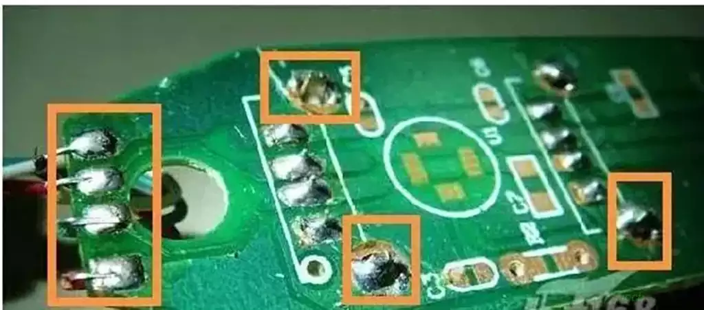
General first look for heating components, such as power tubes, high-current diodes, high-power resistors, integrated circuits, etc., these components are prone to heat because of the virtual welding, serious can be seen directly, minor can be viewed with a magnifying glass. Generally just welded pins are very smooth. When the edge is affected, due to constant extrusion and stretching, will become rough and glossy, around the solder joints will appear gray circle, with high magnification can be seen in the tortoise crack-like small cracks group, the seriousness of the formation of ring-shaped cracks, that is, desoldering. Therefore, even if there is no desoldering in the place of the ring-shaped black circle, it is a hidden danger in the future. Large area of patch welding integrated circuit, heating element pins is one of the solutions. - Current detection method
Check whether the current setting is in line with the process requirements, there is no change in the product load current setting is not correspondingly added, so that the welding current is not enough to produce welding defects. - Shaking method
Is to use the hand or camera on the low-voltage components one by one to shake, in order to feel the components have no loosening phenomenon, which should be mainly on the larger components to shake. In addition, before using this method, should be compressed to the scope of the fault. Determine the approximate scope of the fault, otherwise facing a large number of components. Shaking one by one is very unrealistic. - Vibration method
When encountered when the phenomenon of virtual welding, you can take the method of knocking to confirm, with a screwdriver hand Bing gently tapping the circuit board to determine the location of the virtual soldering points. But in the use of percussion method, should ensure personal safety, but also to ensure the safety of the equipment, so as not to expand the scope of the failure. - Soldering method
Patching method is when a careful inspection still can not be found after the failure of a maintenance method, is the scope of the failure of the components one by one for welding. In this way, although the real fault is not found, but can achieve the purpose of repair.
Component Virtual soldering is a phenomenon in which the connection between the solder joint and the component or circuit board is not strong or reliable due to various reasons during the soldering process. False soldering can lead to circuit failures, signal transmission problems, and unreliability of equipment. Component false soldering may have the following effects:
Unreliable electrical connections: False soldering can lead to unreliable connections between solder joints and components or pcb boards. This can lead to poor current transfer, resulting in circuit failure or degraded performance. Unreliable electrical connections can also lead to instability in signal transmission, affecting the normal operation of the device.
Resistance Changes: Poor connections due to false soldering may result in changes in resistance values. Resistors in a circuit are selected based on design requirements, and false soldering may result in resistance values that are outside the design range, which in turn affects the power consumption and performance of the circuit.
Temperature issues: False soldering may cause poor contact between the solder joints and components or boards, resulting in localized current overload or current imbalance.This can lead to localized temperature increases, which can cause overheating problems and damage to components and boards.
Reliability issues: False soldering may cause the connection between the component and the board to become unstable. Under prolonged use or high workloads, these unstable connections may loosen or break, leading to a decrease in the reliability of the device.
How to prevent causing Virtual soldering and fake soldering?
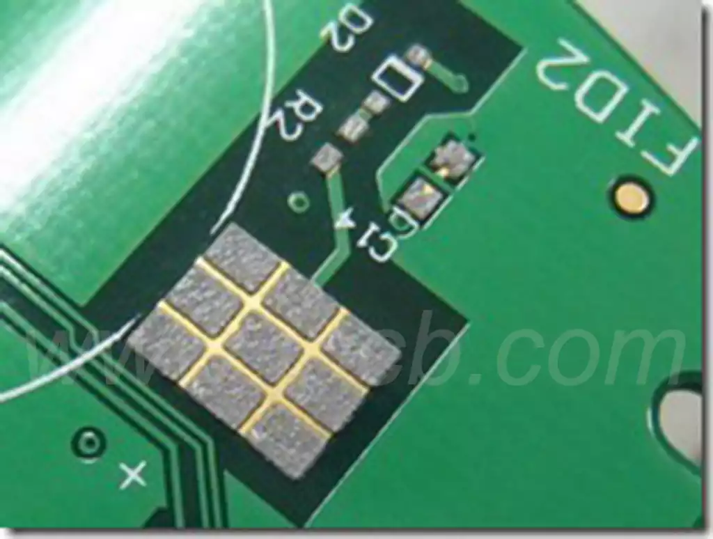
- Defective pad design. There should not be any through holes in the pads; through holes will cause loss of solder resulting in insufficient solder. Pad spacing, area also needs to be standardized to match, otherwise the design should be corrected as soon as possible.
- PCB board oxidation phenomenon, that is, the pads are dark and not bright. If the oxidation phenomenon, the rubber can be used to remove the oxide layer, improve the tin effect.
- PCB board moisture, PCB in the dry box 110 ° baking 8H.
- Select a good active solder paste, the paste should be used up within 24 hours after opening the lid.
- Materials should be stored and transported reasonably according to the requirement of moisture sensitivity to avoid moisture and oxidation.
- According to the product device, PCB layout, material setting reasonable furnace temperature curve.
- Set the parameters of the printing machine and work according to the standard to ensure that the printing effect is OK.