Wave soldering as a key process widely used in the field of electronic manufacturing, the stability and precise control of the process is an important guarantee to ensure the quality of welding.
Wave soldering process control:
(1) flux (solder) spraying
Double-sided tape is used to paste the paper on the surface of the printed circuit board (PCB) for the flux coating operation. Subsequently, check the uniformity of flux spraying to ensure that there is no leakage of spray phenomenon, and to confirm that the flux can effectively penetrate into the holes, especially for organic solder-protection film (OSP) treated holes. Leakage of spray is often a common cause of welding defects such as bridging and tip pulling.
2) Preheating
The preheating step is designed to achieve the following goals:
Promote most of the flux evaporation, to prevent the soldering process due to the flux evaporation and heat absorption, resulting in a sudden drop in the temperature of the tin wave and spattering phenomenon.
Adjust the flux to the appropriate viscosity, to avoid the viscosity is too low to avoid the flux prematurely by the tin wave away, affecting the wetting effect.
Make the printed circuit assembly (PCBA) to reach the appropriate temperature, reduce the thermal shock when entering the solder wave, and reduce board deformation.
Promote flux activation. Appropriate preheating effect is assessed by maintaining the temperature of the soldering surface between 110~130℃. For specific PCBA, can be judged by measuring the component surface temperature or feel (sticky is appropriate, too dry easily triggered by welding problems).
(3) welding process
Turbulent wave should have enough impact to form an irregular pattern of peaks and valleys.
Smooth wave tin surface needs to be kept flat, wave height adjustment to achieve the goal of defect-free welding. Different waveform requirements vary, for example, a brand of wave soldering machine, wave height is easy to bridge, pull the tip (due to insufficient heat); wave height is too high, the fullness of the welded joints decreased (due to rapid pull-down). These phenomena are related to its narrow arc wave characteristics. Pull-tip problem usually stems from the solidification of the solder before the complete pull-down, which may be due to the fast heat dissipation of the lead wire or the lead wire is too long. To avoid spiking, either increase the lead temperature by deepening the smoothing wave press or reduce the transfer speed (at high transfer speeds). Wave height adjustment needs to be coordinated with the transmission speed, adjust the wave height alone is often difficult to achieve the desired results.
(4) transfer speed
Transmission speed affects the heat of the solder joints and separation speed, usually can not be adjusted alone, need to combine the waveform and the characteristics of the PCBA soldered to adjust.
(5) rail width
The width of the guide should be set to the extent that the PCB can slide freely, too tight will exacerbate the deformation of the PCB or even lead to the bow (the emergence of the rules of non-welded areas), while accelerating the wear and tear of the jaws (most of the wave soldering machine relies on the side of the aluminium profile to support the jaws, a small number of models in the side of the inlaid copper strip to improve wear resistance).
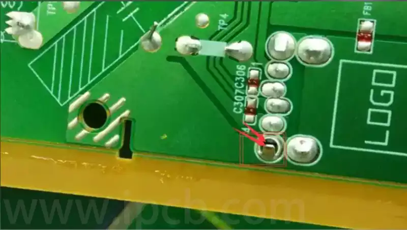
Wave soldering five process control key points
Temperature Control
Preheat temperatures are typically set between 110 and 130 degrees Celsius with a preheat duration of 1 to 3 minutes to activate the active components in the flux and reduce the effects of thermal shock on the board.
The soldering temperature is typically 50 to 60 degrees above the melting point of the solder to ensure that the solder is completely melted, thus avoiding solder joint defects.
Flux Management
Flux density should be maintained in the range of 0.5 to 0.8 grams per cubic centimetre to ensure uniform coverage of the board.
Flux application methods include foam, wave and spray, with the spray method providing a more even distribution of flux and reduced usage.
Waveform and speed control
The height of the wave should be adjusted according to the thickness of the printed circuit board, usually one-half to one-third of the thickness of the board to prevent leakage or excessive tin build-up.
Conveyor speed control between 0.3 and 1.2 metres per second, should be reasonably adjusted according to the actual situation, to avoid welding time is too short or too long to bring quality problems.
Welding environment maintenance
Keep the environment of the welding area clean and stable temperature and humidity to prevent dust, humidity and temperature changes affect the welding effect.
Regularly clean the dross in the wave soldering to prevent the oxides from accumulating and affecting the quality of the solder.
- Equipment configuration and operating requirements
Select equipment equipped with advanced sensors and intelligent control systems to achieve precise process control.
Operators must strictly comply with the operating instructions to ensure that the equipment operates normally and to ensure stable welding quality.
Good control of the wave soldering process depends on all-round detail management, from the uniform spraying of flux to the reasonable setting of preheating temperature, to the coordinated adjustment of the waveform and transmission speed, each link should not be neglected. At the same time, the maintenance of the welding environment and the reasonable application of advanced equipment are also key factors to ensure the welding effect. Only when operators strictly implement the specifications, combined with scientific process parameters adjustment, can achieve stable and efficient wave soldering production.
