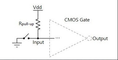
In digital circuits, a pull up resistor (pull up resistors) is a resistive device used to ensure that the input signal is at the desired logic level when an input port has no device connected or is at a high impedance. They usually work between different logic devices to provide a certain voltage signal. Resistors used in logic circuits are used to ensure that pins have well-defined logic levels under all conditions.
Digital logic circuits have three logic states: high, low, and floating (or high impedance). A high impedance state occurs when a pin is not pulled to a high or low logic level, but remains “floating”. A good example is the unconnected input pin of a microcontroller. It is neither in a high logic state nor a low logic state, and the microcontroller may unpredictably interpret the input value as either a logic high or a logic low. Pull up resistors are used to solve the microcontroller’s dilemma by pulling the value to a logic high state.
Pull up resistors can operate when the logic device is not supplying current. An open collector has a pull up resistor, and the output signal of such a circuit is often used in driving external devices, combinational logic circuits, and multiple devices connected to a bus.
Pull up resistors and pull down resistors are resistive components. A pull up resistor is connected to the positive terminal of the power supply, while a pull down is connected to the negative terminal or ground. Pull up is to clamp an uncertain signal at a high level through a resistor, which also acts as a current limiter. Pull down is the same, also will be uncertain of the signal through a resistor clamped at a low level. Pull up is the uncertain signal through a resistor clamped at a high level, the resistor at the same time play a role in limiting current.
In the electronic components, there is no pull up resistor and pull down resistor of the two entities of the resistor, the reason for such a name, the reason is based on the use of different scenarios to define the resistor, the essence of the resistor. Like decoupling capacitance, coupling capacitance, also according to its application to take the name, its essence or capacitance.
Pull up is the uncertainty of the signal through a resistor clamped at a high level, the resistor at the same time play a role in current limitation. The pull down resistor is directly connected to the ground, connected to the diode when the end of the resistor is low, the uncertain signal through a resistor clamped at a low level. Pull up is the input current to the device, pull down is the output current; strong and weak just pull up resistor resistance value is different, there is no strict distinction; for non-collector (or drain) open-circuit output-type circuits (e.g., ordinary gate circuits) to provide the ability to provide current and voltage is limited, pull up resistor function is mainly for the open-collector output output-type circuits to output current channel.
Usefulness and Difference between Pull up Resistors and Pull down Resistors
Usage
Pull up resistors and pull down resistors are mainly used for input ports in digital circuits. They can keep the input port in a high or low state at all times, thus ensuring that the level of the logic gate input port is stabilized. For example, in microcontroller development, when an external key is used to connect to the input port of a microcontroller, pull up resistors or pull down resistors are usually used to ensure that the input port is always in a high or low level state.
Differences
The difference between pull up resistors and pull down resistors is that they serve different purposes. A pull up resistor pulls the input port to a high level, while a pull down resistor pulls the input port to a low level. Therefore, you need to choose whether to use a pull up resistor or a pull down resistor according to your specific needs in actual applications.
The appropriate value of a pull up (or pull down) resistor is limited by two factors. One factor is power consumption. If the resistor value is too low, a high current will flow through the pull up resistor, heating the device and consuming unnecessary power when the switch is closed. This is called a strong pull up and can be avoided when low power consumption is desired. The second factor is the pin voltage when the switch is broken. If the pull up resistor value is too high, coupled with high leakage current at the input pin, the input voltage becomes insufficient when the switch is broken. This condition is called a weak pull up. The actual value of the pull up resistor depends on the impedance of the input pin, which is closely related to the leakage current of the pin.
In addition, the values of the pull up resistor and pull down resistor are different. Generally, the pull up resistor takes a value in the range of 1kΩ~10kΩ, while the pull down resistor takes a value in the range of 10kΩ~100kΩ. This is due to the fact that in digital circuits, the input ports usually show a high resistance state, and the range of values for the pull up resistor and pull down resistor ensures the stability and reliability of the circuits.
In conclusion, pull up resistors and pull down resistors are a very important component in digital circuits, and they ensure the level stability of the input port of a logic gate. When selecting and using pull up resistors and pull down resistors, it is necessary to consider the actual applications and needs, and combine them with other components.
The role of pull up resistors and pull down resistors
Pull up resistors and pull down resistors have a common role: to avoid voltage “levitation”, resulting in circuit instability.
1、Improve voltage alignment
When the TTL circuit drives the CMOS circuit, if the high level of the TTL circuit output is lower than the lowest high level of the CMOS circuit, then it is necessary to connect the pull up resistor at the output of the TTL to increase the value of the output high level; OC gate circuits must be added to the pull up resistor in order to increase the value of the output high level.
2, increase the output pin drive capability
Some microcontroller pins also often use pull up resistors.
3, N/A pin (not connected to the pin) anti-static, anti-interference;
In the CMOS chip, in order to prevent damage caused by static electricity, not used pins can not be suspended, generally connected to the pull up resistor to reduce the input impedance, to provide a leakage path. At the same time, the pin suspension is easier to receive external electromagnetic interference.
4, resistance matching
Reflected wave interference suppression, long-wire transmission resistance mismatch is easy to cause reflected wave interference, plus pull down resistors to match the resistance, can effectively suppress reflected wave interference.
5、Preset space state/default potential
Pull up or pull down resistors are connected to some CMOS inputs in order to preset the default potential. When these pins are not used, these inputs pull down to connect a low level or pull up to connect a high level. The state when the bus is idle such as I2C is obtained by the pull up and pull down resistors.
6. Improve the noise tolerance of the chip’s input signals
Inputs if the high resistance state, or high impedance inputs are in a suspended state, this time you need to add pull up or pull down resistors, so as not to be affected by the random level, which in turn affects the circuit work. Similarly, if the output is in a passive state, you need to add a pull or pull down resistor, such as the output is only the collector of a transistor, so as to improve the chip’s noise tolerance of the input signal to enhance the anti-jamming ability!
1 the concept: an uncertain signal, through a resistor connected to the power supply VCC, fixed at a high level;
2 pull up is to inject current into the device, the irrigation current;
3 When an IO port connected with a pull up resistor is set to input state, it is fixed at high level.
pull down resistor:
1 Concept: An indeterminate signal, connected to ground GND through a resistor, is fixed at low level;
2 Pull down is the output current from the device, pull current;
3 When an IO port connected with a pull down resistor is set to input state, it is fixed at low level. Pull up is to inject current into the device, pull down is the output current, weak and strong just pull up resistor resistance value is different, there is no strict distinction, for non-collector (or drain) open-circuit output-type circuits (e.g., ordinary gate circuits) to enhance the ability to raise the current and voltage is limited, the function of the pull up resistor is mainly for the open-collector output-type circuits to output the current channel.
Disadvantages
The disadvantage of pull up resistors is that they consume extra energy when current flows through them and may cause a delay in the output level. Some logic chips are sensitive to the momentary state of the power supply introduced through the pull up resistor, forcing the configuration of a separate voltage source with filtering for the pull up resistor.
Pull up/down resistor selection
(1) From the perspective of power consumption
The pull up resistor is connected to the power supply, and the pull down resistor is connected to GND. When selecting the resistor, it is necessary to take into account the loss brought about by the resistor itself. For example, in a key circuit, a resistor of 10K can satisfy the conditions, and a resistor of 20K can also satisfy the conditions. However, it is obvious that the energy consumption of the resistor is lower when the resistor is 20K. In circuits where there is a need to treat the machine, it is necessary to strictly control the value of the pull up and pull down resistors.
(2) From the viewpoint of driving capability
The size of the driving capability is related to the current supplied. For example, in OC-gate and OD-gate circuits, if the pull up resistor is taken too large, it will not be able to provide a large current to the back stage when the output level is high. As shown in the figure below, the LED requires 5-10mA of current for normal operation, if the resistor is taken too large, the LED cannot be lit, so the pull up resistor needs to be selected in combination with the current and voltage of the LED.
(3) From the point of view of signal rate in the IIC bus need to increase the pull up resistor, pull up resistor is too large, will slow down the signal from low to high level transition time, the rising edge becomes slower, affecting the signal rate.
Why Use Pull Resistor
Generally, if the IC itself does not have an internal resistor when used as a single-key trigger, another resistor must be connected outside the IC in order to keep the single-key in a non-triggered state or to return to the original state after triggering. Digital circuits have three states: high level, low level, and high resistance state, some applications do not want to appear in the high resistance state, you can pull up resistors or pull down resistors to make the way in a stable state, depending on the design requirements. Generally speaking, I/O port, some can be set, some can not be set, some are built-in, some need external, the output of the I/O port is similar to a transistor C, when C is connected through a resistor and the power supply is connected together, the resistor becomes the upper C pull down resistor, that is to say, if the port is normally a high level, the C is connected through a resistor and the ground is called pull down resistor, so that the port is high level. Called pull down resistor, so that the port is normally low, the role of: for example: when a port connected to the pull up resistor is set to lose such as state, his normal will be high, used to detect low-level inputs. Pull up resistor is used to solve the bus drive capacity is insufficient to provide current. The general term is pull current, pull down resistors are used to absorb current, which is often referred to as current sinking.