In the complex process of PCB design, PCB layout and PCB routing are two core stages that together determine the final performance and reliability of the product. However, during the design process, many engineers often fall into the trap of “focusing on routing and neglecting layout,” overlooking the foundational role that layout plays in PCB design.
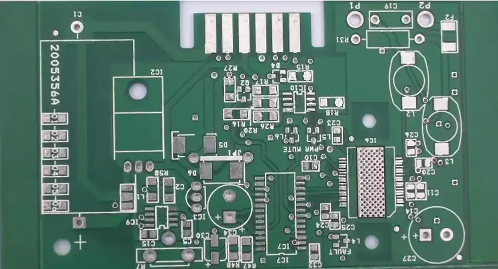
PCB Layout is the first step in PCB design, and its core involves determining the placement, spacing, orientation of all components on the PCB based on product function and component characteristics, as well as the partitioning of power and ground planes. Essentially, it’s about “planning the overall architecture of the PCB.” PCB Routing, on the other hand, occurs after the layout is finalized, connecting the component pins through traces to enable signal transmission. It essentially “completes the details of the architecture.”
In simple terms, layout determines the PCB’s “genetic makeup,” while routing affects its “postnatal development.” If the layout is designed reasonably, with scientific component placement, clear signal path planning, and proper power and ground plane division, routing can proceed smoothly, requiring only minor adjustments to meet performance requirements.
On the other hand, if the layout is chaotic—such as placing high-frequency components next to sensitive components, clustering heat-generating components, or having overly long power traces—no amount of routing adjustments will fully resolve issues like signal interference, uneven heat dissipation, and even signal loss and EMC risks, which may worsen due to excessive routing.
The core requirements for PCB design are to achieve “stable signals, efficient heat dissipation, manufacturing feasibility, and controlled costs.” These four requirements are almost entirely determined by the layout, while routing can only make minor tweaks within the framework set by the layout, unable to surpass the limits set by the layout. This is the most critical reason why layout is more important than routing.
Signal Transmission
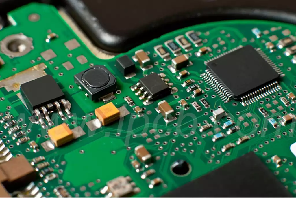
From a signal transmission perspective, layout directly determines the length, direction, and potential interference between signals. For products that require high signal integrity, such as high-frequency PCBs and industrial control PCBs, the longer the signal path, the greater the signal loss and delay. When high-frequency components are placed next to sensitive components (like analog devices or sensors), electromagnetic interference (EMI) can easily occur, leading to signal distortion. These issues need to be avoided during the layout phase. Once the layout is set, the signal path and component spacing are essentially fixed, and routing can only connect within that predefined space, unable to fix fundamental layout issues, such as routing high-frequency signal lines across analog lines. No matter how much the routing width is adjusted, interference cannot be completely eliminated.
Heat Dissipation
From a heat dissipation perspective, the reasonableness of the layout directly impacts the PCB’s heat dissipation efficiency. Power components, CPUs, and other components on the PCB generate a significant amount of heat. If these heat-generating components are clustered together during layout, it can lead to localized overheating, accelerating component aging, and even causing product failure. A well-designed layout, on the other hand, will distribute the heat-generating components, placing them near the edges of the PCB or heat sinks, and ensuring enough space for heat dissipation. While routing can also influence heat dissipation (such as thicker traces providing better heat dissipation), this effect is much less significant than layout—no matter how thick the traces are, it cannot solve the overheating problem caused by clustering heat-generating components together.
Manufacturing Feasibility
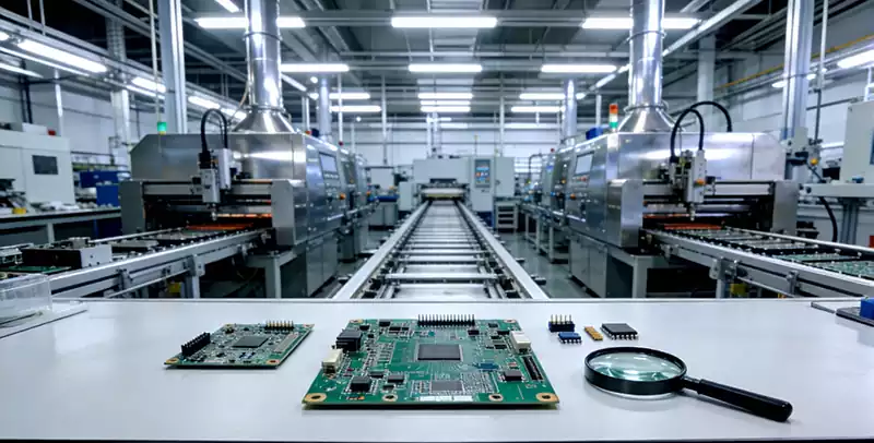
From the perspective of manufacturing feasibility, layout directly determines the production difficulty and yield of the PCB. If the component spacing is too small, issues like solder bridging or poor solder joints can arise during SMT assembly. If the component orientation is not reasonable, it can affect the efficiency of through-hole mounting and soldering. If the layout does not take into account PCB manufacturing processes (such as the reserved areas for solder mask or silkscreen), it may lead to difficulties during production. These problems are not solvable by routing—once the layout is unreasonable, the issues are already present during the production stage. Even with meticulous routing, production difficulties cannot be resolved and, in fact, may increase PCB layer count and cost due to excessive routing.
In real-world PCB design scenarios, there are numerous cases where ignoring layout has resulted in routing rework and product failures. This further confirms the central importance of layout. Based on the industrial PCB and consumer electronics PCB cases we have handled, these pain points are especially prevalent.
For instance, an industrial control device customer reported frequent system crashes and signal instability in their self-designed PCB. Engineers spent two weeks optimizing routing, adjusting signal trace paths and widths, but the issue remained unresolved. Upon intervention by our technical team, the root cause was found to be in the layout design: the high-frequency control chip was placed adjacent to the analog sensor, and the power trace was too long, resulting in high-frequency interference and excessive power ripple that impacted chip operation. Even though routing adjustments were made with shielded traces and optimized trace spacing, interference couldn’t be fully eliminated. Eventually, we adjusted the layout: separating the high-frequency chip from the analog sensor, shortening the power trace, and optimizing the ground plane. No significant changes to the routing were needed, and the product failures were completely resolved, with the production yield improving from 60% to 98%.
Another consumer electronics client, designing a PCB for a wearable device, prioritized miniaturization and densely placed all components. During layout, they didn’t account for heat dissipation or signal interference. During routing, engineers spent a lot of time optimizing traces, but the product testing revealed that the device would crash after running for 10 minutes due to overheating, and the Bluetooth signal was unstable. After investigation, the core issue was a layout flaw: the CPU was densely clustered with the battery and power components, leaving insufficient space for heat dissipation, and the Bluetooth antenna was placed too close to the power traces, causing signal interference. Ultimately, we optimized the layout, redistributed the components, created space for heat dissipation, and adjusted the spacing between the Bluetooth antenna and the power traces. Routing was only adjusted minimally, resolving both the overheating and signal issues while still controlling the device’s compact design.
These cases demonstrate that layout is the “source” of PCB design. Once there’s an issue at the source, subsequent routing optimizations can only address the symptoms, not the root cause. Many engineers fall into the trap of “focusing on routing and neglecting layout” because they fail to realize that the flaws in the layout cannot be compensated for by routing. A well-planned layout, on the other hand, can make routing much easier, even reducing up to 80% of routing rework.
Key Principles for PCB Layout
Since pcb layout is more important than pcb routing, what should PCB design engineers focus on during the layout phase? Based on key principles and industry practice, we’ve summarized four essential guidelines that can help avoid layout issues and make routing easier.
1.Partitioned Layout for Isolation
Divide the PCB into different regions based on the function and signal characteristics of components, such as high-frequency, analog, digital, and power regions. Ensure sufficient isolation between different regions to avoid signal interference. For example, high-frequency components (such as Bluetooth and Wi-Fi chips) should be placed in a separate area, away from analog components (such as sensors and amplifiers). The power region should be placed near power components to reduce power ripple.
2.Efficient Heat Dissipation by Distributing Heat-Generating Components
Power components, CPUs, and other heat-generating parts should be spread out to avoid clustering. Place them near the edges of the PCB or near heatsinks, and ensure there are channels for heat dissipation. If space is limited, use copper pours or thermal vias to enhance heat dissipation. Additionally, heat-sensitive components (such as capacitors and sensors) should be placed away from heat sources to prevent temperature interference.
3.Minimize Signal Path Length
Optimize the layout to shorten critical signal paths (such as high-frequency and analog signals) to reduce signal loss and latency. Avoid signal traces crossing each other or excessive routing to ensure stable signal transmission. For example, clock and control signal paths should be as short as possible and placed away from sources of interference.
4.Consider Manufacturing Processes to Ease Production
During layout, consider the requirements for SMT assembly, through-hole mounting, and soldering processes. Ensure the component spacing meets production standards (usually no less than 0.5mm) and that component orientations are optimized for easy assembly and soldering. Additionally, reserve sufficient space for silkscreen and solder mask layers to facilitate accurate production. Also, consider the number of PCB layers and plan power and ground planes to reduce routing difficulty and PCB cost.
Emphasizing the importance of layout over routing does not diminish the value of routing. It simply clarifies the sequence and core roles of the two—layout is the foundation, and routing is the complement. Both need to work together to create high-performance, reliable, and manufacturable PCB products.
In practice, layout and routing are not completely separate; they must adapt and adjust dynamically. During the layout phase, engineers should consider the feasibility of routing and leave enough space for routing to avoid situations where the layout is visually appealing but impossible to route. During the routing phase, if layout issues are identified (such as excessive routing or signal interference risks), slight adjustments to the layout can be made to achieve the best balance. However, these adjustments will always be “minor tweaks within the layout framework” and cannot alter the core layout structure, further emphasizing that the layout is the core of PCB design, determining the overall performance and success of the product.
For PCB routing optimization, the key is to “follow the layout and optimize the details”: optimizing trace width and spacing, avoiding overly long or thin traces, using differential pairs or shielded traces to reduce signal interference, and improving power and ground planes to enhance signal integrity and heat dissipation. These techniques only work within the layout framework, and without a reasonable layout, even the best routing techniques cannot deliver optimal results.
Layout is the foundation of PCB design, establishing the product’s performance and manufacturing feasibility. Engineers should pay attention to layout, follow key principles to plan effectively, and then complement with appropriate routing to create high-quality PCB products.