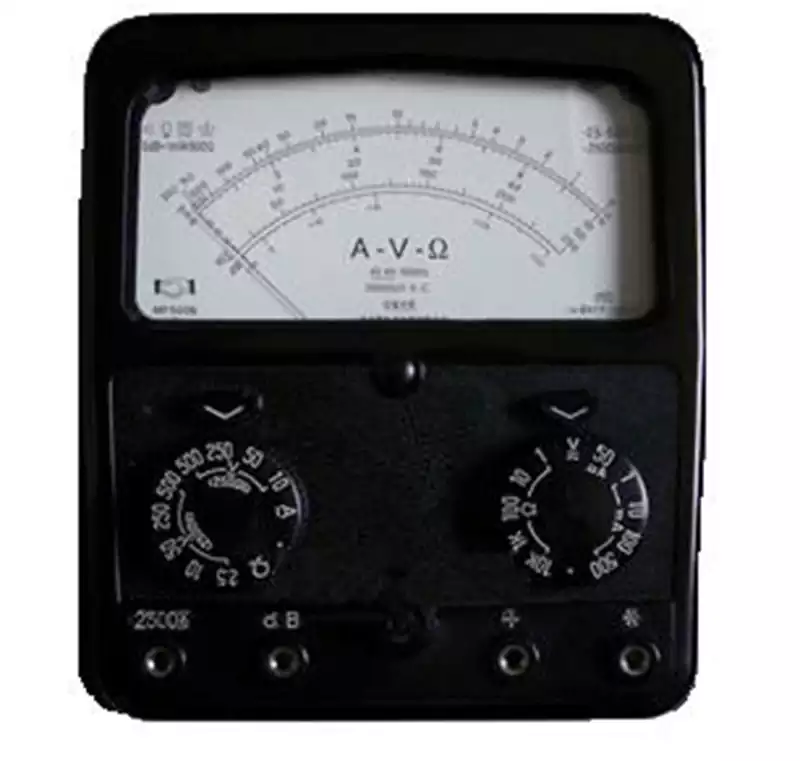
In the daily maintenance and troubleshooting of electronic equipment and electrical systems, the reliability of the switch, as a key component of the circuit control, directly affects the safety and stability of the entire system. The multimeter, as an essential testing tool for electricians, has become an important ‘tool’ for us to test the performance of a switch by virtue of its versatile functions and easy operation. But how to test a switch using a multimeter?
The basic principle of testing a switch with a multimeter
Conductivity Measurement: The conductivity of a circuit is determined by checking whether there is current in the circuit. When the circuit is on, the multimeter will beep or display the on indication.
Resistance Measurement: Set the multimeter to the resistance position, connect the probes of the multimeter to the two ends of the switch respectively, and measure its resistance value. If the resistance value is within the normal range (usually a few ohms to tens of ohms), it means that the switch conducts normally.
How to test a switch using a multimeter?
Multimeter calibration: Set the multimeter to resistance measurement and select the appropriate range according to the expected resistance range of the switch to be tested.
Safety disconnect: Before testing, be sure to disconnect power from the circuit connected to the switch under test to eliminate the risk of electric shock.
On-off state test: Use the red and black pens of the multimeter to contact the two terminals of the switch respectively. When the switch is in the off position, the multimeter should show a high resistance value or infinity. When the switch is closed, the resistance value should decrease significantly and approach zero ohms.
Evaluation of Results: If the test results match the description above, the switch is functioning properly. If it does not, consider replacing the switch.
Detailed Methods and Steps for Multimeter to Measure Switch Leakage
Preparing Tools and Setting Up the Multimeter
Firstly, you need to prepare a multimeter and the appropriate test circuit. Ensure that the multimeter is in normal working condition, and select the appropriate gear according to the testing needs. Generally speaking, you should choose the AC voltage gear when measuring leakage and adjust the range to a suitable range.
Connecting the test line
Next, you need to connect the test line correctly. Firstly, connect the red pen of the multimeter to one of the terminals of the switch, and the black pen to the ground wire or the zero wire of the power supply. This way, when the switch is switched on, if there is a leakage, the corresponding voltage value will be displayed on the multimeter.
Conducting a leakage test
After connecting the test wiring, it is time to perform the leakage test. First, make sure the switch is off and then observe the reading on the multimeter. If the reading is zero or close to zero, it means that there is no leakage when the switch is off.
Next, open the switch and watch the reading on the multimeter change. If the reading increases significantly and stabilises at a certain value, it means that there is leakage in the switch in the on state. At this time, the specific value of the leakage voltage should be recorded for subsequent analysis and processing.
Analysing test results and dealing with leakage
Based on the test results, it is possible to determine whether the switch has a leakage problem and the severity of the leakage. If the leakage voltage is high or exceeds the safety standard, immediate measures should be taken to deal with the leakage problem, such as replacing damaged switching components and strengthening grounding measures.

How to test a switch using a multimeter?
Evaluating the performance of switching tubes (transistors)
A switching tube is a special type of transistor that has a current on/off control function. The following are the steps to test a switch using a multimeter:
Multimeter Configuration: Switch the multimeter to diode test or resistance measurement.
Safety disconnect: Make sure the power supply is completely disconnected before testing.
Forward resistance measurement: Connect the red pen of the multimeter to the base (B) of the switching tube, and the black pen contacts the emitter (E) and collector (C) respectively. A relatively small resistance value should be measured under forward bias conditions.
Reverse resistance measurement: Subsequently, swap the positions of the red and black pens to perform the test. Under reverse bias conditions, a larger resistance value should be measured.
Result analysis: By comparing the forward and reverse resistance values, the state of the switching tube can be initially judged. If the forward resistance value increases abnormally or the reverse resistance value decreases abnormally, it may indicate that the switching tube has been damaged.


