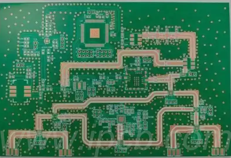
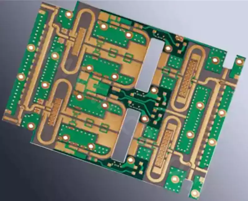
Rogers PCB materials, owing to their unique properties, have become a critical choice in the manufacture of high-frequency electronic equipment. They find extensive application in wireless communication systems, satellite communication devices, radar systems, and microwave antennas. Their exceptional low loss, low dielectric constant, low dielectric loss factor, and outstanding dimensional stability enable Rogers PCBs to deliver outstanding performance in high-frequency environments. Employing Rogers materials during PCB assembly not only optimises signal transmission reliability and range but also enables higher integration and performance in multilayer stack designs.
Rogers PCB is typically employed in high-frequency electronic equipment, such as wireless communication systems, satellite communication devices, radar systems, and microwave antennas. Its characteristics—low loss, low dielectric constant, low dielectric loss factor, and excellent dimensional stability—enable outstanding performance in high-frequency environments.
During PCB assembly, utilising Rogers PCB materials offers the following advantages:
- Low loss: Rogers PCB materials exhibit low dielectric loss characteristics, minimising energy dissipation during signal transmission. This is crucial for high-frequency applications, enhancing signal reliability and transmission range.
- Thermal stability: Rogers PCB materials resist deformation and degradation in high-temperature environments. This makes them highly suitable for thermal applications such as aerospace and automotive electronics.
- Dimensional Stability: Rogers PCB materials exhibit outstanding dimensional stability, maintaining their shape and dimensions across varying temperature and humidity conditions. This is vital for applications demanding high precision and reliability.
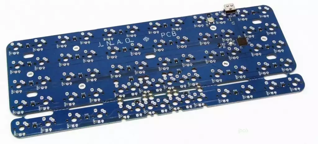
- Multilayer Stacking: Rogers PCB materials support multilayer stacking. By combining different layers of material and circuit boards, higher integration and performance can be achieved.
Preparatory Work for Rogers PCB Soldering
- Material and Tool Preparation
Select suitable soldering materials: Silver-containing solder paste, such as Alpha 903, is recommended to ensure soldering quality and conductivity.
Tool selection: Employ a laser soldering machine to precisely control soldering temperature and duration.
Auxiliary materials: Prepare necessary flux and cleaning tools, such as anhydrous ethanol and lint-free cloths.
- PCB Pre-Treatment
Clean PCB surface: Wipe the PCB surface with anhydrous ethanol to remove grease and contaminants.
Inspect PCB flatness and integrity: Ensure the PCB shows no significant warping or damage.
Oven treatment: Where required, bake the Rogers PCB to remove moisture and enhance substrate stability. - Component Preparation and Layout
Component selection: Choose suitable components, avoiding excessively heavy or large parts to minimise stress on the Rogers PCB.
Layout planning: Strategically arrange components according to circuit design to ensure performance and reliability.
Pre-assembly inspection: Conduct a pre-assembly check before formal soldering to verify component correctness and consistency.
Detailed Guide to Power Connection for Soldering Circuit Boards
Preparatory Work
Prior to soldering the circuit board, prepare all necessary tools and materials, including soldering equipment, power cables, and power plugs. When selecting power cables and plugs, pay close attention to their rated voltage and current to prevent circuit board malfunction or power overload.
Connection Procedure
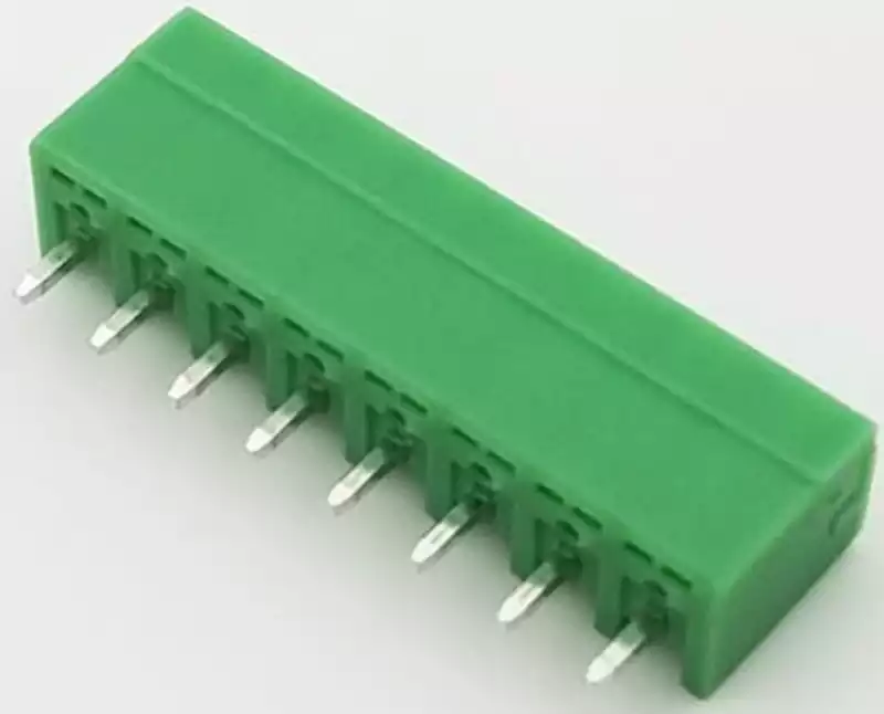
- Strip a section of the power cable to expose the three internal wires: live, neutral, and earth.
- Connect the three wires to the corresponding terminals on the circuit board: the live wire to the ‘+’ terminal, the neutral wire to the ‘-’ terminal, and the earth wire to the ‘GND’ terminal.
- Insert the power plug into a mains socket to activate the power supply.
- Use a multimeter to verify that the voltage on the circuit board remains stable within the normal range. Address any anomalies promptly.
Precautions
- Pay close attention to the polarity of the power cable during connection; reverse polarity may cause the circuit board to malfunction or sustain damage.
- When soldering, ensure the correct tools and techniques are used to prevent weak joints or short circuits.
- Verify all soldered connections are correct before powering up to avoid circuit board burnout.
- When operating the circuit board, observe its rated voltage and current specifications to prevent exceeding its load capacity, which may cause malfunction or damage.
Rogers PCB materials, renowned for their exceptional high-frequency properties, have become indispensable components in modern high-frequency electronic equipment. Through meticulous preparation and proper soldering techniques, one can not only maximise their performance advantages but also ensure the stable and reliable operation of the equipment.