What is an amplifier board?
As the name implies, an amplifier PCB is a circuit that can “amplify” a specific input signal. Amplification means obtaining an enhanced signal gain using an electronic circuit. Amplitude gain is usually calculated by obtaining the ratio of the output signal and the input signal. The most common amplifier component is the transistor, which is a semiconductor device that can amplify a signal and is widely used in switching applications.
An amplifier is a general term used to describe a circuit that produces and increases its version of the input signal. But not all amplifier circuits are the same, as they are classified according to their circuit configuration and mode of operation.
In “electronics”, small signal amplifiers are commonly used devices because they are able to amplify relatively small input signals, such as from sensors (such as optoelectronic devices) into larger output signals to drive relays, lights or speakers for example.
There are many forms of electronic circuits that are classified as amplifiers, from operational amplifiers and small signal amplifiers to large signal and power amplifiers. The classification of an amplifier depends on the size of the signal, its physical configuration, and how it processes the input signal, that is, the relationship between the input signal and the current flowing in the load.

There are many types of amplifier boards, designed according to their use and function. Here are some types that are common in many electronic products.
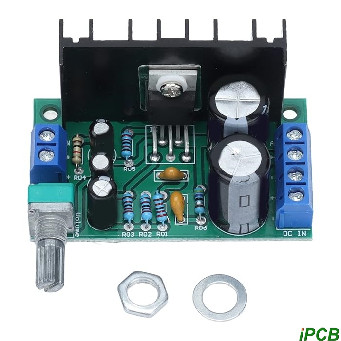
- Power amplifier board. A power amplifier circuit PCB is an electronic board that is used to increase the power size of an input signal. An example is an audio power PCB amplifier, when you have a microphone signal that you want to hear from an audio speaker. In this case, the power amplifier board will need to provide high current, which is good for both amplification and sound filtering.
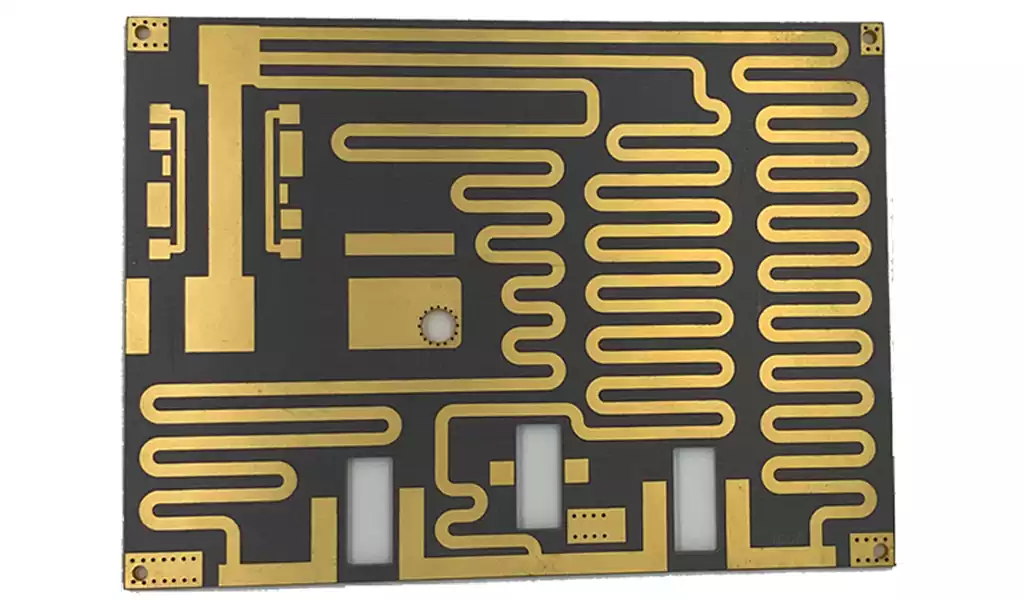
- Microwave power amplifier board. This type of amplifier circuit PCB is used to enhance and amplify microwave signals, making signal transmission more efficient and with higher fidelity over long distances. The power required to transmit from a base station depends on the distance between microwave antennas. When designing a microwave power PCB amplifier, it is important to carefully select the appropriate transistors and perform tests to evaluate actual performance.
- Audio amplifier board. Audio amplifiers may be a familiar device for tech-savvy people with a keen interest in music. Audio PCB amplifiers can improve sound quality and increase volume. Audio amplifier circuit PCBs can be divided into classes A, B, C, and D, with class A being the simplest type with the lowest efficiency and class D being the most efficient with zero output power loss.
- Operational amplifier board. An operational amplifier circuit PCB is an amplifier device that can perform certain “operations” on a specific signal, such as summing, integrating, differentiating, filtering, etc., so that it can modify the input signal. An operational amplifier circuit PCB is more suitable for low output power devices such as headphones.
The basic use of an operational amplifier is to act as a voltage amplifier or comparator. It can also be configured as a filter, phase shifter, buffer (voltage follower), etc. Today, operational amplifiers are often used to amplify weak analog signals from sensors in various Internet of Things (IoT) devices and home appliances.
Operational amplifiers are often used with negative feedback to reduce the product variation of gain and extend the bandwidth. Typical applications of operational amplifiers include non-inverting amplifiers, inverting amplifiers, and voltage followers
Advantages of amplifier boards
Many applications rely on amplifier boards to provide reliable and practical solutions. Some of the advantages are listed below.
- Signal enhancement and power improvement. The real meaning of an amplifier PCB is to improve power quality and enhance input signals. It can control and match signals to provide excellent performance.
- Large bandwidth and low noise. High voltage amplifier boards provide large signal bandwidth and low output noise. In addition to these advantages, the circuit board is also protected against short circuits and overvoltage.
- Cost-effectiveness. Due to the maturity and standardization of the technology, amplifier boards have the advantage of cost-effectiveness. The amplifier circuit PCB consists of inexpensive power semiconductor devices and can be easily integrated into small and simple systems.
- Small PCB devices. The materials and design of the amplifier board are selected to meet the size specifications of the electronic products.
Different Applications of Amplifier Boards
Below are a few of the many relevant applications that amplifier boards can be used for. - Aerospace. Communications in aerospace applications such as spacecraft and satellites require automatic transmission of data and remote control systems. These systems should establish a connection between the aircraft and facilities on earth. The radio frequency signals in these systems are amplified by amplifier boards.
- Consumer electronics. An obvious example of the application of amplifier boards in consumer electronics is audio speakers. Audio speakers consist of an amplifier board that amplifies the sound signal. The signal voltage is increased, allowing increased current to pass through, making the speaker louder.
- Automotive. Advanced automotive systems also make extensive use of electronic devices to achieve various functions, such as enhanced sound systems. The vehicle’s infotainment system is equipped with an amplifier board, and its main design goal is to minimize the amplifier size and reduce the thermal load. The power amplifier board for automotive applications is also used for start-stop engines. At the same time, operational amplifiers are also used in automotive LED applications and backlight control.
Tips for wiring amplifier PCBs
During the circuit design process, application engineers often overlook the layout of the printed circuit board (PCB). A common problem is that the circuit schematic is correct, but it does not work, or only works at low performance. I will show you how to properly layout the operational amplifier board to ensure its functionality, performance, and robustness.
The next time you lay out a printed circuit board, it is recommended that you follow the following layout conventions:
- Minimize the connection of the inverting pin.
- Place the decoupling capacitor as close to the power pin as possible.
- If multiple decoupling capacitors are used, place the smallest decoupling capacitor closest to the power pin.
- Do not place vias between the decoupling capacitor and the power pin.
- Extend the routing path as much as possible.
If you want to lay out your PCB in the future, be sure to follow these guidelines:
- Make sure all lines on the input are fully balanced;
- Reduce line lengths and minimize capacitance on gain setting pins;
- Place the reference buffer circuit as close to the INA reference pin as possible;
- Place decoupling capacitors as close to the power pins as possible;
- Cover with at least one solid ground plane;
- Don’t sacrifice good layout for silkscreen electronic components ;
A method for manufacturing a power amplifier board, characterized in that the method comprises:
grooving a substrate to form a groove on the substrate;
roughening the surface of the grooved substrate to form a surface treatment layer;
filling an insulating medium into the groove and covering the surface treatment layer, placing a printed circuit board on the insulating medium, and then performing a pressing process together, and joining the printed circuit board and the substrate through the insulating medium;
drilling and copper-plating downward from the surface of the printed circuit board after the pressing process to form a plurality of blind holes for signal connection between the top conductive layer of the printed circuit board and the substrate, or between the top conductive layer of the printed circuit board and one of the other conductive layers except the top conductive layer;
grooving downward from the printed circuit board after the pressing process into the substrate to form a sunken groove.
Key considerations in amplifier board design and manufacturing
Designers and manufacturers must pay attention to the following factors in amplifier board circuit design.
- Component selection. We need to consider the PCB layout of the amplifier PCB design. The design must consciously pay attention to the selection of components to achieve the best performance of the amplifier board. Surface mount devices (SMDs) can be selected to obtain low lead inductance for these component types. This technology prevents unnecessary inductance and capacitance. SMDs are small in size and enable compact designs.
- Signal integrity. This is something we need to pay attention to in PCB amplifier circuit design. Signal lines should also be properly planned, using microstrip and stripline whenever possible to ensure signal integrity. Signals must be undisturbed to reduce electrical noise. This is achieved through proper amplifier board layout, signal distribution, and EMI shielding.
- Heat dissipation. Devices used for amplification generate heat when in operation. The amplifier circuit PCB design has cooling mechanisms to eliminate overheating and maintain its reliable performance. Since localized heating can cause system failures and device malfunctions, the amplifier board design should have heat sinks and channels to dissipate heat effectively and efficiently.
- Stability. This is another factor we need to consider in PCB amplifier circuit design. Sufficient gain and linearity are not the only important aspects of this type of PCB, stability is also a key consideration. Stability is the amplifier circuit PCB to resist unstable oscillations. Evaluate the stability of the amplifier board circuit by checking the input amplitude and output reflection coefficient.
At iPCB, we are committed to providing customers with good products. We have extensive experience in amplifier boards. Whether you need design, production, or software development, we can do it for you here.


