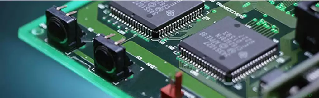
UPS PCB, short for uninterruptible power supply printed circuit board, is the core control board of the UPS system. It is primarily responsible for providing emergency power to equipment when the main power supply is interrupted.
UPS PCBClassification
⑴ Offline Square Wave Output UPS Power Supply: Its single-unit output power is approximately 400–2000 VA. When the mains voltage is within the range of 162–268 V and the frequency is within 45–55 Hz, it supplies the load with general mains power processed through a transformer tap, at which point the inverter is in automatic shutdown mode. When the mains voltage is below 162V or above 268V ±5%, or the frequency is below 45Hz or above 55Hz ±1Hz (the frequency range for generators is wider), it provides the user with a 50Hz square wave power supply with voltage regulation characteristics.
⑵ Standby (off-line) sine wave output UPS power supply: Its single-unit output power is approximately 500–3000VA. When the mains voltage is within the range of 160–281V and 45Hz–55Hz, it supplies the load with general mains power processed through the transformer tap, at which point the inverter is in automatic shutdown mode. When the mains voltage is below 160V or above 281V ±4%, or the frequency is below 45Hz or above 55Hz ±1Hz (the frequency range for generators is wider), it provides users with a 50Hz sine wave power supply featuring voltage regulation.
⑶ Online UPS circuit board: Its single-unit output power ranges from 0.7 to 1500 kVA. When users adopt a multi-unit ‘redundant’ parallel configuration scheme, they can directly parallel several to dozens of UPS power supplies with the same output power and model to form a large-scale UPS power supply system with an output of 7000 to 8000 kVA. Online UPS provides users with high-quality pure sine wave power.
There are also two categories of non-centralion/phoenixtec mainstream products
⑷ Interactive UPS power supply: Its single-unit output power ranges from 0.7 to 20 kVA. When the mains voltage is within the range of 180 to 240 V, it directly supplies mains power to the load via an AC bypass formed by a transmission cable. When the mains voltage is within the range of 150–180V or 240–276V, it provides the user with mains power of 197–250V through an AC voltage regulator composed of a transformer tap voltage regulation circuit. Only when the mains voltage is below 150V or above 276V does it provide the user with true inverter sine wave power. It is also known as a quasi-online UPS.
⑸Delta Conversion Type UPS Power Supply: Its single-unit output power ranges from 10 to 480 kVA. When the mains power supply meets the voltage fluctuation requirements of ≤±15% and frequency fluctuation requirements of ≤±3 Hz, the compensation power supply provided by the Delta converter, which does not exceed 15% of the inverter’s rated output voltage, is connected in series with the main power supply circuit via a compensation transformer, forming a series voltage-regulated power supply together with the input power supply. When the input power is outside the aforementioned voltage and frequency ranges, the main converter (without an inverter output isolation transformer) provides a sine wave power supply to the user.
GB/T14715-93 Classification by output capacity: Those below 3 kVA are classified as micro UPS, 3–10 kVA as small UPS, 10–100 kVA as medium UPS, and those above 100 kVA as large UPS.

The UPS PCB consists of several main subcircuits that work together:
AC-DC rectifier/battery charger
The rectifier converts AC power from the mains or backup generator into stable DC power for battery charging and supplies the DC bus. This not only charges the battery but also maintains the correct float voltage and safe charging curve.
Precise regulation prevents undercharging or overcharging even with significant input fluctuations. Protective features prevent excessive current. A multi-stage design optimises the charging cycle, reduces charging time, and maximises battery life.
DC-AC Inverter
The inverter efficiently converts DC power from the rectifier or battery into clean AC power waves to supply connected devices. Exceptional stability ensures output remains stable even with moderate power fluctuations. The professional UPS inverter topology can actively correct more severe voltage sags or spikes by adjusting the pulse width modulation waveform until input changes stabilise.
Static Bypass Switch
When the UPS malfunctions or overloads, the system directly transfers regulated mains power to the output, preventing connected loads from losing power. The static bypass PCB board features automatic unlocking functionality, enabling true fault-tolerant capability—a stark contrast to traditional electromechanical contactors that require manual reset. This provides critical redundancy functionality.
Battery Bank
Valve-regulated lead-acid batteries are the most economical and compatible batteries for UPS energy storage needs. While lithium-ion batteries offer higher performance, they come at a higher cost. Regardless of the battery type used, the UPS PCB coordinates safe charging configurations while monitoring health metrics such as internal impedance to issue maintenance alerts.
Control/Monitoring System
Advanced UPS PCB designs integrate programmable microcontrollers to drive user interfaces with interactive menus, advanced diagnostics, and event logging capabilities, while also supporting remote monitoring via a network. Control loops optimise transient response across various operating modes. Intelligent design not only aids maintenance but also enhances visibility into equipment and power status.
Some key design considerations for UPS PCB:
1. Voltage and power management:
Ensure that the PCB can handle the input voltage range and provide a stable output voltage.
Select the appropriate component size to support the maximum load wattage.
Optimise efficiency to reduce power loss and heat generation.
Implement line and battery regulation to ensure voltage stability.
2. Transmission and Waveform Quality:
Design for fast, seamless transmission between the power source (line to battery).
Ensure the purity of the output waveform meets device requirements.
Minimise transmission speed to reduce downtime.
3. Protection and Safety:
Include protection mechanisms such as overvoltage, undervoltage, overcurrent, and short-circuit protection.
Implement safety features to protect the UPS and connected devices.
Comply with safety and EMC standards.
4. Environmental Considerations:
Consider operational environmental factors, including ambient temperature and altitude.
Select components capable of withstanding specified environmental conditions.
Integrate thermal management to prevent overheating.
5. Reliability and Component Selection:
Focus on component selection to prevent derating and extend service life.
Add conservative design margins to enhance robustness and reliability.
Calculate and aim for a high Mean Time Between Failures (MTBF).
By considering these design factors during PCB design, you can develop a UPS system that provides reliable, efficient power backup while meeting the safety and performance requirements of connected devices.
Functions of the UPS PCB:
Power Management:
AC-DC Rectification and Battery Charging: The rectifier on the UPS PCB converts the input AC power into regulated DC power for battery charging and supplying the DC bus. It also ensures precise regulation of the battery across a wide range of input voltage fluctuations, preventing overcharging or undercharging, and optimising the charging cycle to extend battery life.
DC-AC Inverter: The inverter efficiently converts DC power from the rectifier or battery into clean AC power waves to drive connected devices. The customised UPS inverter topology can actively correct severe voltage sags or spikes by adjusting the pulse width modulation waveform until the input stabilises.
Voltage Regulation: The UPS PCB stabilises the output voltage regardless of whether the power source is mains or battery, which is critical for protecting sensitive equipment from voltage spikes or sags.
Power Switching:
Static Bypass Switch: When the UPS fails or is overloaded, the static bypass switch routes regulated mains power directly to the output to prevent power interruption to connected loads. This automatic, non-locking operation provides true fault tolerance, unlike traditional electromechanical contactors that require manual reset, thereby offering important redundancy.
Power Switching Control: The UPS PCB includes dedicated circuits to detect mains power interruptions and can quickly and automatically switch power from mains to battery power, and vice versa.
Battery Management:
Battery Health Monitoring: The UPS PCB coordinates safe charging profiles while monitoring battery health metrics, such as internal resistance, to issue alerts when maintenance is required. It also ensures batteries operate at optimal conditions and prevents overcharging or deep discharge, thereby extending battery lifespan.
System Monitoring and Communication:
Control/Monitoring System: The precision UPS PCB design integrates a programmable microcontroller that drives the user interface, providing interactive menus, advanced diagnostics, and event log recording, while supporting remote monitoring via a network. These control loops optimise transient response across various operating modes and assist maintenance by enhancing visibility into device and power status.
The UPS PCB is the core component ensuring the efficient and reliable operation of uninterruptible power supply systems. It integrates complex power management, precise battery control, rapid power switching, and comprehensive system monitoring functions to provide stable, clean power to connected devices.
As technology advances, future UPS circuit boards will become smarter, more efficient, and more compact. With growing demands for higher energy efficiency, longer battery life, and stronger interoperability, UPS PCB design will continue to evolve to meet changing industry standards and user expectations, providing more stable and reliable power protection for critical applications.