Multilayer ceramic capacitor (MLCC) is constructed by stacking extremely thin ceramic dielectric layers with electrodes (typically nickel) printed upon them in an offset arrangement.
Composition of multilayer ceramic capacitor:
Ceramic dielectric: Under an electric field, polarised dielectric materials store energy. Their polarisation constant changes with variations in the electric field. Different dielectric types exhibit varying response speeds and polarisation constants due to their distinct primary polarisation mechanisms.
Inner Electrode: Alternating with ceramic dielectric layers, it provides the positive electrode plate area.
PME-Ag/Pd: Primarily used in X7R and Y5V high-voltage MLCC product series, featuring high material costs.
BME-Ni: Currently dominant in most products, offering low material costs but requiring reduction atmosphere sintering.
Terminal Electrodes
Base Layer: Copper or silver metal electrodes connecting to the internal electrodes to conduct capacitance.
Barrier Layer: Nickel plating providing thermal barrier properties; the solderable nickel barrier prevents tin layer melt-off during soldering.
Solder Layer: Tin plating forming the solderable metal interface.
Multilayer Ceramic Capacitor Manufacturing Process:
- Batch Preparation
Ceramic powder, binder, solvent, and various additives are blended in specific proportions. After ball milling or sand milling for a defined duration, a uniform and stable ceramic slurry is produced. This slurry constitutes a relatively complex system, typically comprising ceramic powder, solvent, dispersant, binder, plasticiser, and defoamer.
Among these, ceramic powder serves as the core material, determining the fundamental properties of the multilayer ceramic capacitor (MLCC). The binder, a polymer resin, maintains spacing between ceramic particles while imparting strength. The solvent comprises toluene and ethanol blended in a specific ratio. The dispersant, a surfactant, prevents agglomeration and clumping caused by surface electrostatic forces, ensuring stable dispersion of the ceramic powder. Additives are incorporated to modulate the electrical properties of the ceramic powder itself, meeting specific reliability requirements for the product and ensuring the sintering process proceeds smoothly.
- Casting
The ceramic slurry is extruded from the casting machine’s nozzle and uniformly coated onto a continuously advancing silicone film, forming a thin layer of ceramic slurry with consistent thickness. Subsequently, this layer traverses a hot-air zone where the majority of solvents in the ceramic slurry evaporate under the influence of hot air. Through this heating and drying method, a film of uniform thickness and density meeting specifications is ultimately formed (typically with film thicknesses ranging from 1μm to 20μm).
During the forming process, two primary roll-to-roll extrusion methods are employed. The On-roll method is typically employed for thick film production, utilising a slit die for extrusion. During operation, precise alignment is required between the rear roller’s centreline and the die’s extrusion point. The Off-roll method is generally used for thin film production, where the die’s extrusion point is positioned above the rear roller’s centreline. The substrate is coated with slurry before contacting the rear roller; this method is also known as the air cushion or web coating technique.
During the forming and drying stage, parameters such as line speed, temperature, and pump flow rate must be adjusted to facilitate the evaporation of most solvents from the ceramic slurry. This induces film shrinkage and densification, achieving the appropriate thickness and film density.
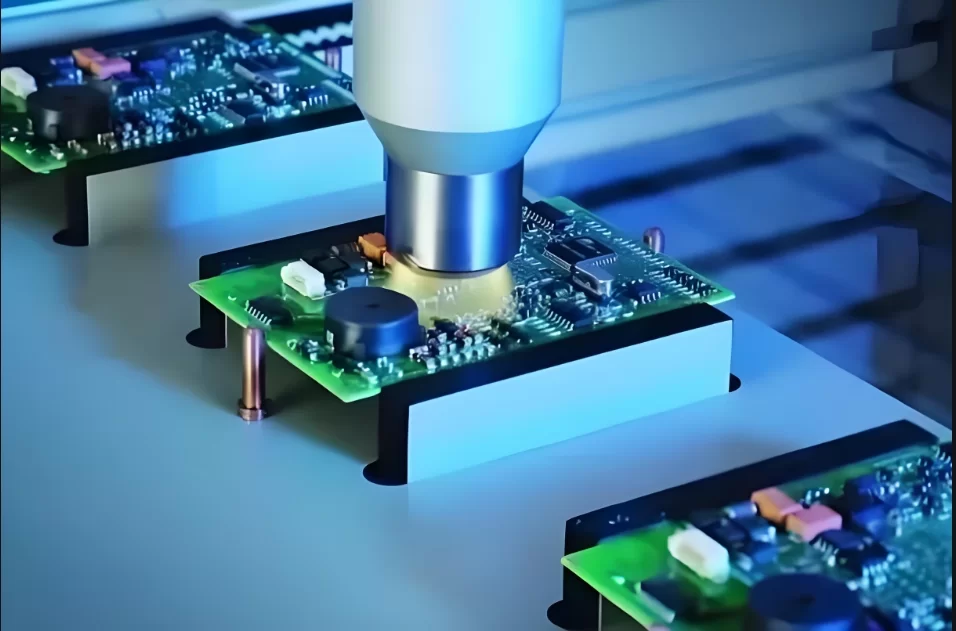
- Printing
The internal electrode paste is printed onto the ceramic membrane via a screen printing plate. After drying, a clear and complete dielectric membrane is obtained.
Printing methods exist:
Letterpress printing: Internal electrode paste is applied to raised areas and printed under pressure.
Gravure printing: Internal electrode paste is applied across the entire plate, with printing occurring only in the recessed areas.
Planographic printing: Utilises the repulsion between water and oil, where the plate surface is coated with inner electrode paste for printing.
Screen printing:
Involves printing after the inner electrode paste is expelled through the mesh openings.
Compared to gravure printing, screen printing offers lower equipment and tooling costs, higher paste utilisation with minimal waste, reduced electrode pattern bleed, and flexible screen design. Consequently, most manufacturers employ printing methods similar to SMT solder paste dispensing. Compared to gravure printing, screen printing offers lower equipment tooling costs, higher paste utilisation with minimal waste, reduced electrode pattern bleed, and flexible screen design. Consequently, most manufacturers employ a printing method similar to SMT solder paste or red glue application, using a screen printing plate to deposit the internal electrode paste onto ceramic film. Some manufacturers utilise printing presses, passing the ceramic film through a paste reservoir to deposit the metallic paste onto the ceramic substrate.
- Lamination
As the fourth stage in the manufacturing process of multilayer ceramic capacitor (MLCC), lamination serves the core function of stacking printed dielectric sheets in a specific staggered arrangement to form a uniformly thick bar. Following the printing stage, sheets are cut and separated from their substrates before entering the lamination phase. During stacking, ceramic film protective layers are added to both the bottom and top surfaces of the stack. This enhances the product’s mechanical strength and improves its insulation properties.
This process demands strict control over multiple critical parameters, including stacking temperature, applied pressure, and dwell time. Precise alignment accuracy for the offset positions must also be maintained, alongside ensuring the cleanliness of the working environment. Consequently, the lamination process is typically conducted within a cleanroom environment.
- Pressing
The printed and laminated bar is subjected to uniform hydrostatic pressure at a constant temperature. This process ensures the individual laminated layers within the bar bond tightly together, enhancing the density of the sintered ceramic body and achieving a more cohesive structure. Pressure, holding time, and temperature are critical quality factors (CTQs) requiring stringent control. Uniform pressure distribution is paramount, making water-based pressing the optimal method. Quality assurance involves slicing and sampling to verify pressing uniformity and bonding integrity.
Primary lamination workflow:
Pellets → Sealed bag → Lamination press → Pressurisation/heating → Cooling → Bag removal.
- Cutting
In accordance with product design specifications, the laminated bar is cut using a thin-bladed slicer. This performs transverse and longitudinal cutting operations according to preset dimensions, dividing the bar into individual, completely separated chips (the capacitor blanks).
The cutting principle operates as follows: when the blade initiates the downward cutting action on the wafer, the blade holder drives the blade downward. Upon contact with the wafer surface, the blade holder maintains downward pressure, forcing the sharp cutting edge to shear through. Under the combined influence of the blade holder’s force and the blade’s own inertia, when the cutting edge reaches the surface of the PET adhesive layer, the blade holder rapidly retracts upward, completing a full cutting cycle.
- Degassing
Degassing refers to the thermal treatment of cut ceramic blanks to remove organic substances such as adhesives. For nickel electrode multilayer ceramic capacitor (MLCC), when air is used as the degassing environment, the temperature is typically around 250°C, though specific temperatures vary based on product dimensions and formulation differences. When nitrogen is employed for degassing, the temperature can be set higher, typically between 400°C and 500°C.
The primary degassing procedure involves: first loading the blanks into designated containers and arranging them → subsequently transferring them into the degassing furnace for treatment → finally retrieving the degassed blanks from the furnace.
- Sintering
The sintering process transforms degassed chips into ceramic bodies characterised by complete internal electrodes, excellent density, dimensional accuracy, high mechanical strength, and superior electrical properties. This process comprises two stages: densification and re-oxidation.
Sintering is conducted within an atmosphere furnace, typically at temperatures ranging from 1100°C to 1350°C. Given the high-temperature environment, nitrogen/hydrogen gas is introduced into the furnace to prevent oxidation. Critical factors include maintaining suitable and uniform temperatures throughout the furnace chamber, achieving thermal equilibrium, and ensuring adequate air circulation to promote uniform and dense crystalline phase growth within the ceramic body.
The primary sintering workflow is as follows: chips are first arranged appropriately → then transferred into the furnace for sintering → removed from the furnace upon completion → finally unloaded from the container.
- Chamfering
Chamfering, also termed grinding in the process, is necessary because capacitors exhibit sharp, protruding edges after sintering into ceramic form. This condition impedes effective connection with external electrodes, necessitating grinding and chamfering treatment. The chamfering process involves placing the capacitors, along with water and grinding media, into a chamfering tank. Through agitation methods such as ball milling or planetary grinding, burrs are removed from the ceramic chip surface, rendering it smooth and clean while fully exposing the internal electrodes at the end faces. Key control parameters for this process are rotational speed, duration, and temperature, with inspection focusing on parameters such as dimensional accuracy, curvature, and exposure rate.
The primary chamfering workflow is as follows: first, batch preparation → followed by chamfering treatment → subsequent cleaning of processed capacitors → removal from the tank after cleaning → finally, drying operation.
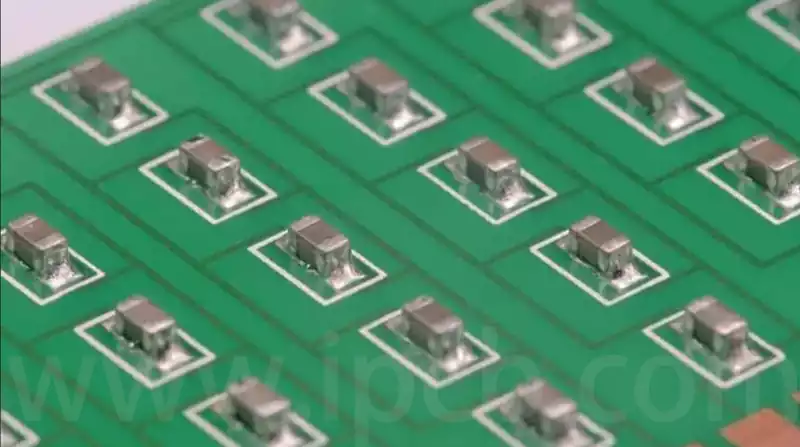
- End-sealing
Using an end-sealing machine, end paste is applied to both ends of the exposed internal electrodes on the chamfered chip. This connects the internal electrodes on the same side to form external electrodes.
Primary end-sealing process: Chip insertion → Paste application → Drying → Extraction. - Firing
At approximately 750°C under nitrogen-air atmosphere, sometimes with humidification, the organic binder in the end-electrode paste is fully combusted. The glass body melts and impregnates the copper powder, solidifying the ends and forming a robust bond with the ceramic body and internal electrodes. - Electroplating
Post-firing terminal processing essentially involves electroplating. Specifically, the product is immersed in an electrolyte solution containing nickel and tin metal ions. The MLCC terminal electrode is designated as the cathode, and a low-voltage direct current is applied. This causes nickel and tin metal ions to continuously deposit onto the cathode, ultimately forming a nickel layer and a tin layer on the terminal electrode surface.
The nickel layer serves to: enhance the capacitor’s resistance to thermal shock, protect the external electrodes, and prevent alloying between the external electrodes and tin (Sn).
The tin layer functions to: improve the capacitor’s solderability, ensuring the multilayer ceramic capacitor chip is securely soldered to the PCB during surface mounting processes.
- Testing
Products undergo 100% testing and sorting across four performance parameters: capacitance, loss, insulation, and withstand voltage. Defective items are rejected, while functional units are sorted into distinct capacitance ranges.
Primary test parameters: capacitance, loss, withstand voltage, and insulation.
- Visual Inspection
Capacitors undergo examination of their external morphology, with substandard products removed.
Primary identification criteria: Appearance defects, dimensional anomalies.
- Tape-and-Reel
The tape-and-reel process involves loading tested multilayer ceramic capacitor chips onto carrier tape, then winding them onto a plastic reel in specified quantities. This operation facilitates large-scale, high-speed automated placement during SMT production while preventing multilayer ceramic capacitor breakage from mutual impact during transport. Furthermore, to prevent cross-contamination of different materials, capacitance testing is typically conducted again on each MLCC during the tape-and-reel process. - Packaging
The packaging stage encompasses affixing identification labels and packing products prior to shipment. For multilayer ceramic capacitor manufacturers, labels applied after tape-and-reel processing usually contain only the manufacturer’s own information. During packaging, additional labels bearing customer details and barcodes are added to facilitate customer identification.
The primary packaging workflow is as follows: first affix labels to the trays; then place products into boxes and affix labels to the boxes; finally, place the boxes into cartons and affix labels to the cartons. Subsequent packaging stages generally employ automated management systems for inspection, utilising barcode scanning for automatic verification to effectively prevent material mix-ups or errors.
The manufacturing of multilayer ceramic capacitor (MLCC) constitutes a complex process involving multiple intricate stages. From initial material preparation to final packaging, each step is intricately interconnected, collectively determining the product’s ultimate performance and quality. Only through rigorous control of parameters and quality across all process stages can superior MLCC products meeting market demands be produced, thereby propelling the continuous advancement of the electronics industry.